3-22 Wiring
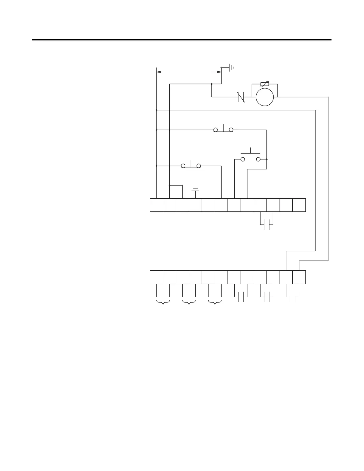
Figure 3.21 Typical Retrofit Wiring Diagram
➀
Customer supplied.
➁ Overload protection should be disabled in the SMC-Flex controller.
➂ Refer to the controller nameplate to verify the rating of the control power input voltage.
➃ Soft Stop, Pump Stop, or Brake.
➄ Aux #2 should be set to N.O.
Note: Refer to Chapter 3 for typical power circuits.
11 12
13
14
15 16
17
18 19 20
21
23
24
25 26
27
28 29
30 31 32 33
22
34
Option Stop
Start
M
OL
Alarm
Contact
Fault
Contact
Aux #2
Normal
Aux #1
Normal/Up-to-Speed/
Bypass
SMC-Flex
Control Terminals
Control Power
Stop
PTC
Input
TACH
Input
Ground
Fault
➀
➄
➀
➀
➂
➀➃
➀➁

 Loading...