3-12 Wiring
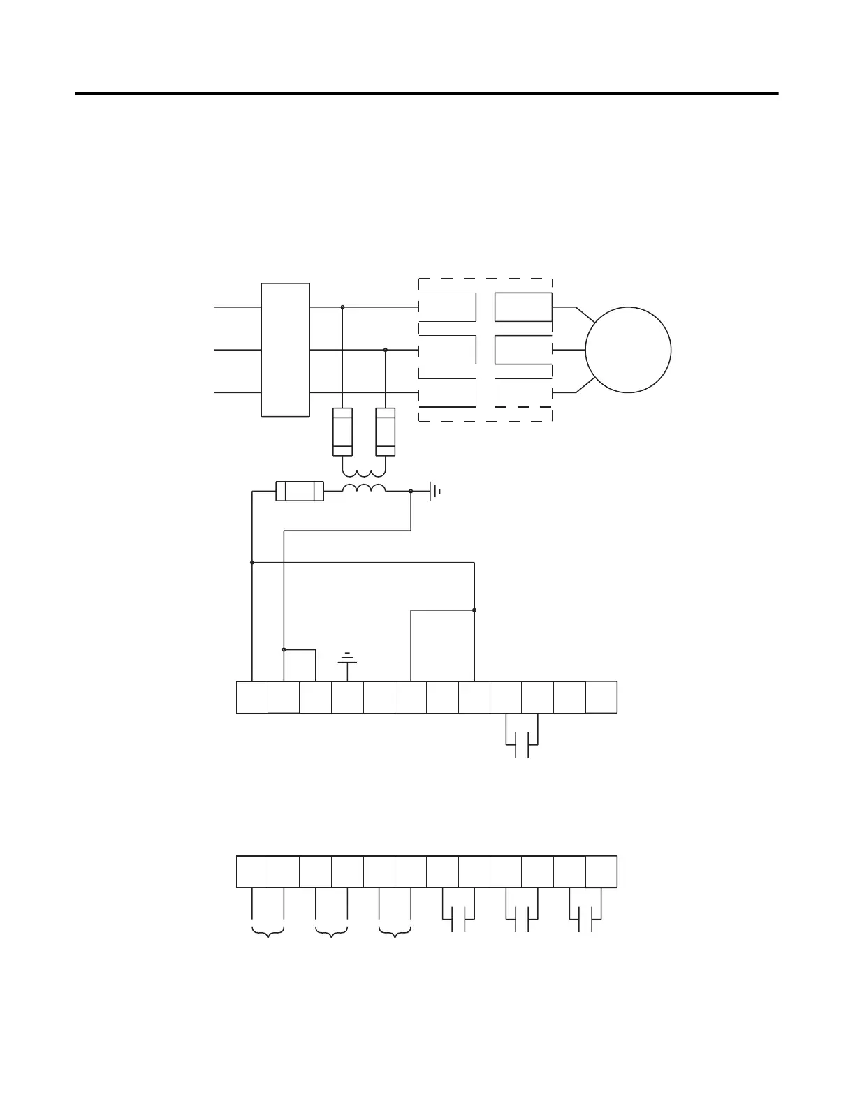
Figure 3.11 Typical Wiring Diagram for Start-Stop Control via DPI
Communications
Note: Use this wiring diagram when start-stop will come from
either a Bulletin 20-HIM LCD interface module or a
Bulletin 20-COMM communication module connected to the
SMC-Flex.
Note: Logic mask must be properly configured, see Chapter 8.
➀
Customer supplied.
➁ Refer to the controller nameplate to verify the rating of the control power input voltage.
11 12
13
14
15 16
17
18 19 20
21
23
24
25 26
27
28 29
30 31 32 33
22
34
L1/1
L3/5
L2/3
T3/6
T2/4
T1/2
M
3-Phase
Input Power
Branch
Protection
SMC-Flex
Controller
Alarm
Contact
Fault
Contact
Aux #2
Normal
Aux #1
Normal/Up-to-Speed/
Bypass
SMC-Flex
Control Terminals
PTC
Input
TACH
Input
Ground
Fault
➀
➀
➀
➀
➀
➁

 Loading...