Specifications and Site Requirements
Electrical Specifications
148 MagneMotion
Rockwell Automation Publication MMI-UM007F-EN-P - September 2020
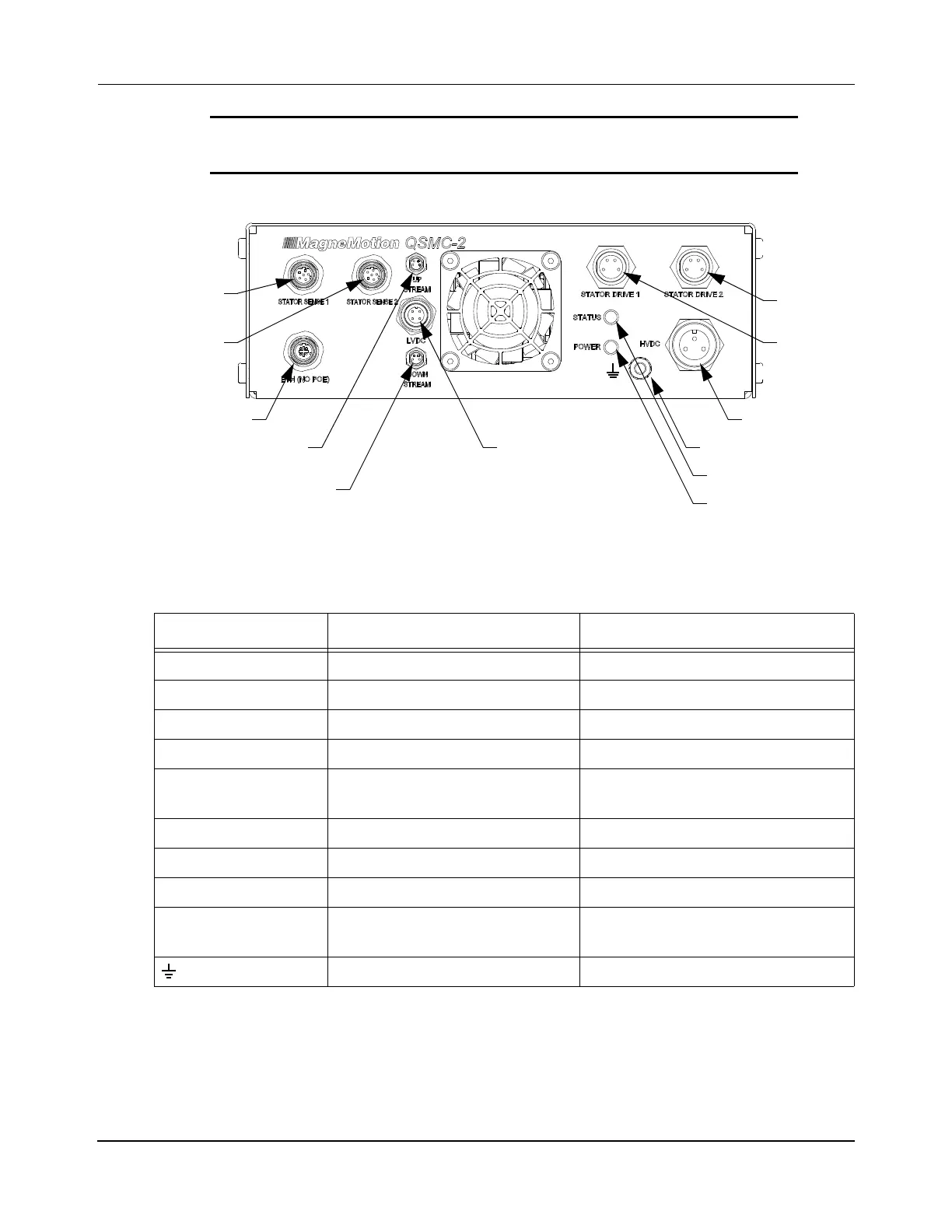
Figure 4-17: QSMC-2 Motor Controller Electrical Connections
NOTICE Hot-plugging of either power source to the motor controller
is not recommended.
Table 4-22: QSMC-2 Motor Controller Connections
Label Description Connector Type
STATOR SENSE 1 Motor block control signals M12 Eurofast, FKFD 4.6, Female
STATOR SENSE 2 Motor block control signals M12 Eurofast, FKFD 4.6, Female
ETH (NO PoE) Ethernet – 10/100/1000 BaseTx M12 Eurofast, FKFDD, 4-Pin, Female
UP STREAM RS-422 motor communications M8 Nano-Mizer, 4-Pin, Male
*
* When using an NC LITE, MagneMotion recommends connecting the upstream connections to the odd num-
ber connectors on the node controller and the downstream connections to the even number connectors.
LVDC (logic power) 24V DC ±5%,
0.6 A typical, 0.75 A max
M12 Eurofast, FSFD 4.4, Male
DOWN STREAM RS-422 motor communications M8 Nano-Mizer, 4-Pin, Male
*
STATOR DRIVE 1 Motor block phase power Mini-Con-X, 4-Pin, Female
STATOR DRIVE 2 Motor block phase power Mini-Con-X, 4-Pin, Female
HVDC (motor power) 270V DC min, 400V DC max,
5 A typical, 15 A max
A-size Powerfast, 3-Pin, Male
Ground M6 threaded stud
†
† MagneMotion requires grounding the QSMC-2 through the ground stud using a minimum of 14 AWG wire.
Status Indicator
Front View
Stator 1
Stator 2
HVDC Power
Power Indicator
LVDC Power Ground
Sense
Drive
RS-422
Downstream
Stator 1
Drive
Stator 2
Sense
Ethernet
RS-422
Upstream
 Loading...

