Installation
Transport System Installation
QuickStick HT User Manual 197
Rockwell Automation Publication MMI-UM007F-EN-P - September 2020
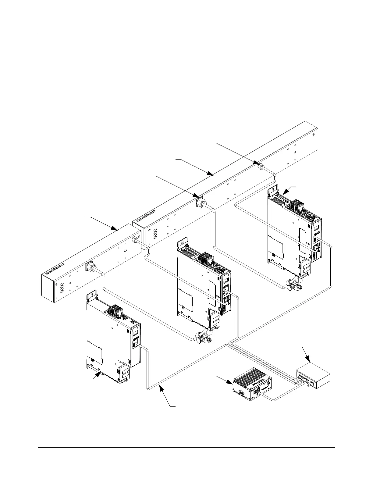
See Figure 4-9 for the connection locations on the QSHT motors and Figure 4-20 for the con-
nection locations on the QSHT 5700 inverters. See the Node Controller Hardware User Man-
ual, MMI-UM013, for the communication connection locations on the node controllers. See
Figure 5-10 for a detailed example.
When connecting the inverters to the node controllers, both ends of a path do not need to con-
nect to the same node controller. However, all connections to the inverters for motors at the
ends of all paths that meet in a node must be made to the same node controller. See the Quick-
Stick Configurator User Manual, MMI-UM009, for more information about nodes and paths.
Figure 5-10: QSHT Motor and QSHT 5700 Inverter Communications Connections
Sense Connector
Node
1/2 m QSHT
QSHT 5700
Inverter
D
o
w
n
s
t
re
a
m
(typical)
Power Connector
(typical)
U
p
s
t
r
e
a
m
1m QSHT
Controller
Network
Switch
2198-Pxxx
DC Bus
Power Supply
Ethernet Cable
(typical)
 Loading...

