Installation
Transport System Installation
210 MagneMotion
Rockwell Automation Publication MMI-UM007F-EN-P - September 2020
3. Insert DC-bus end-caps that on the first and last modules on the bus to cover exposed
terminals
4. Connect the LVDC power-bus connector to the terminals on the power supply and to
the first QSHT 5700 inverter.
• See the Kinetix 5700 Servo Drives User Manual, 2198-UM002 for bus installa-
tion.
5. Repeat Step 4 for each inverter in the power chain.
NOTE: It is not necessary to connect all motors on a path to the same power supply
or to connect a power supply to only one path.
6. Make sure that all NC LITE node controllers are mounted to grounded surfaces.
7. Make sure that the ground stud on all NC-12 node controllers is connected to GND
(PE).
8. Make sure that all NC-E and NC-S node controllers are grounded through the chassis
ground connection in their power connectors.
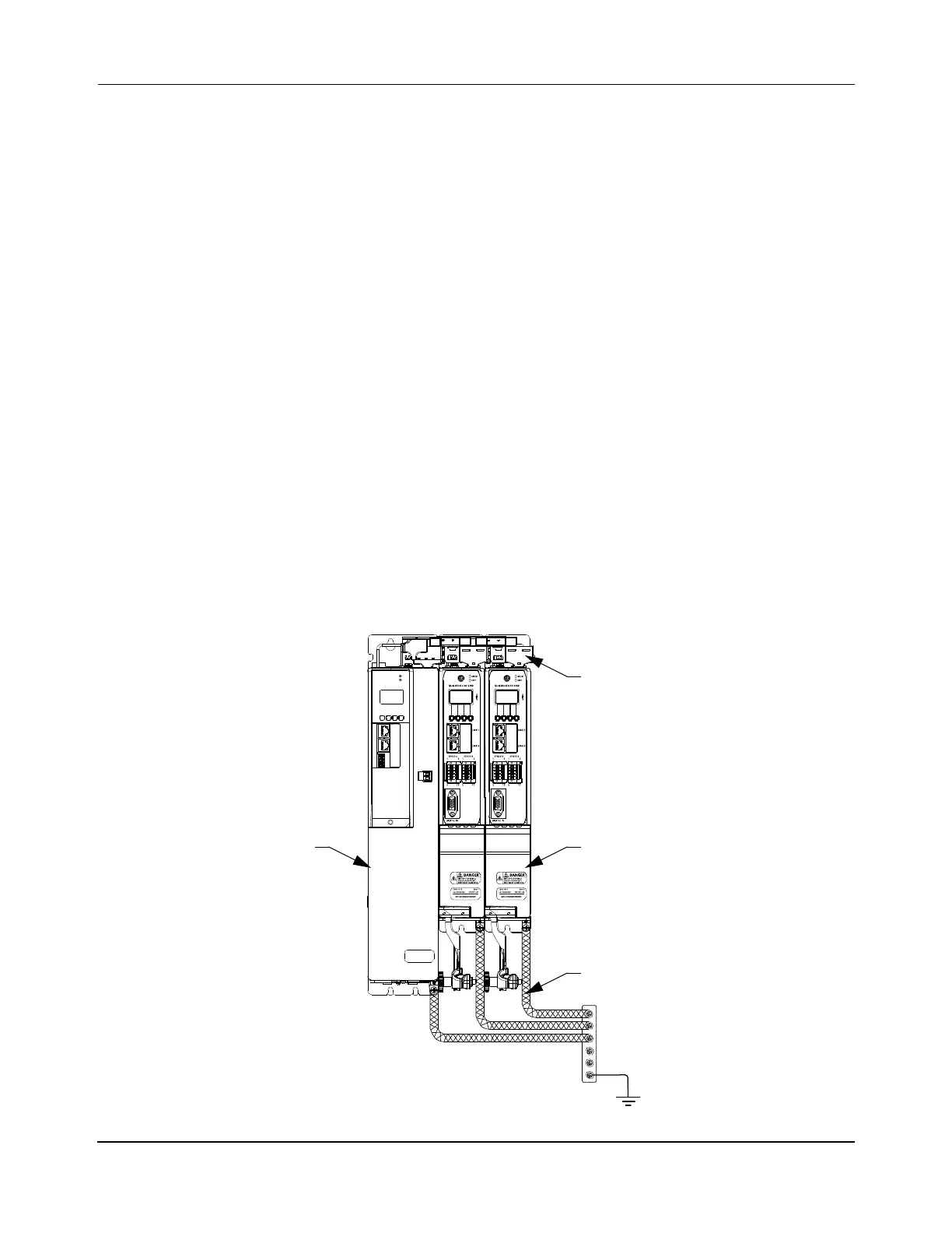
9. Bond DC-bus power supplies, inverter modules, capacitor modules, and line filter
grounding screws by using a braided ground strap as shown in Figure 5-17.
10. See Facilities Connections on page 214 for external power connections.
Figure 5-17: QSHT 5700 Inverter Grounding
QSHT 5700 Inverter
(typical)
2198-Pxxx PS
(typical)
Shared-bus Connection Systems
(DC-bus and 24V DC)
Braided Ground Strap
(typical)
 Loading...

