102 Rockwell Automation Publication 7000-UM202H-EN-P - November 2023
Chapter 2 Power Component Definition and Maintenance
Test Points
The yellow LED (LED 1) on the SGPDB indicates that the controlled SCR has a
gating current flowing, which turns on the SCR.
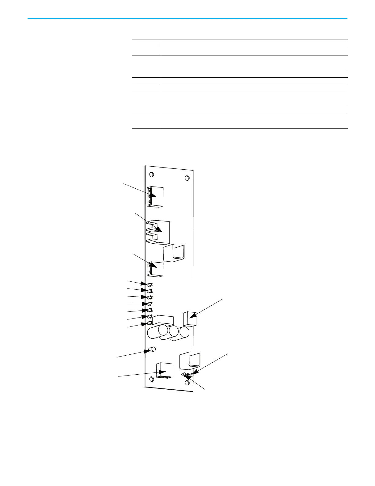
Figure 91 - Self-Powered Gate Driver Board
TP1 SCR gate output (attach oscilloscope between TP1 and TP2 to see gating pulses)
TP2 SCR cathode output
TP3
Common reference point for all other test point measurements, except for TP1, which uses TP2 as
its reference point
TP4 The positive 20 V rail used for the SPGDB operation
TP5 The positive 5 V rail used for the SPGDB operation
TP6 The sense voltage taken from the sense resistor across the SCR being controlled
TP7
Trigger signal, which remains active for a fixed period of time after the SCR being controlled, has
turned on and the voltage across it has collapsed
TP8 Internal gating signal that indirectly turns on the SCR that is being controlled
TP9
Gating signal received from the commanding drive control board, through the appropriate fiber
optic cable
TB3 - Test Power Connection
OP1, OT1 - Fiber Optic Transmitter and Receiver
TB2 - Temperature Sensor Power Connection
TP9
TP8
TP7
TP6
TP5
TP4
TP3
Status Indicator
TB1 - Snubber Connection
TB4 - Gate and Cathode
Thyristor Connection
TP2
TP1

 Loading...


