80 Rockwell Automation Publication 7000-UM202H-EN-P - November 2023
Chapter 2 Power Component Definition and Maintenance
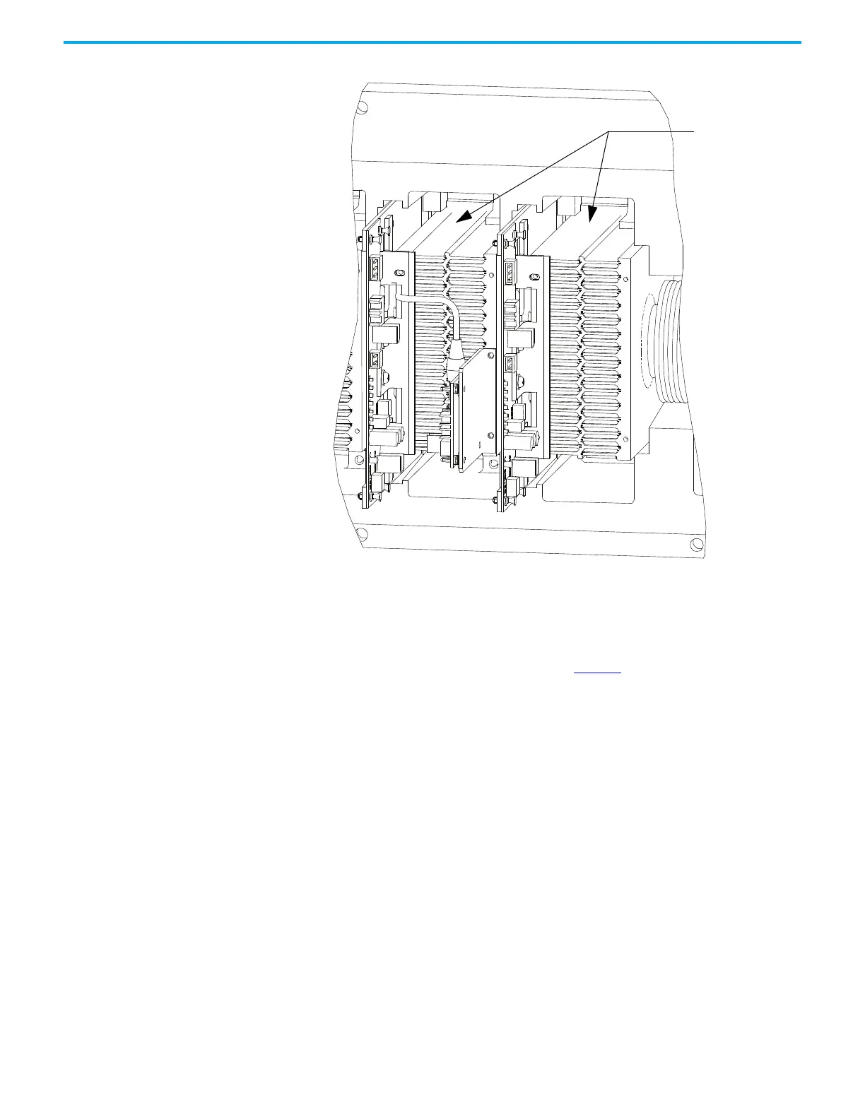
Figure 73 - Anode-to-Cathode test
A good SCR and circuit should read between 22 and 24 kΩ.
An SCR that has failed from anode-to-cathode will commonly produce a
resistance value of 0 for a shorted device or
∞Ω for an opened device. Unlike
the SGCT, it is highly irregular for an SCR to have a partially shorted device. If
an SCR is found to be out of tolerance, see page 85
for detailed instructions on
how to replace the SCR assembly.
SCR Sharing Resistance Test
To test the sharing resistor of an SCR module, disconnect the 2-pole plug of the
self-powered gate driver board labeled SHARING and SNUBBER on the circuit
board. The red wire of the plug is the sharing resistor. Measure the resistance
between the red wire of the plug and the heatsink to the left. A value of 80 k-
ohms indicates a healthy sharing resistor.
Resistance value
between two
heatsinks is
Anode-to-Cathode
resistance

 Loading...


