Rockwell Automation Publication 7000-UM202H-EN-P - November 2023 67
Chapter 2 Power Component Definition and Maintenance
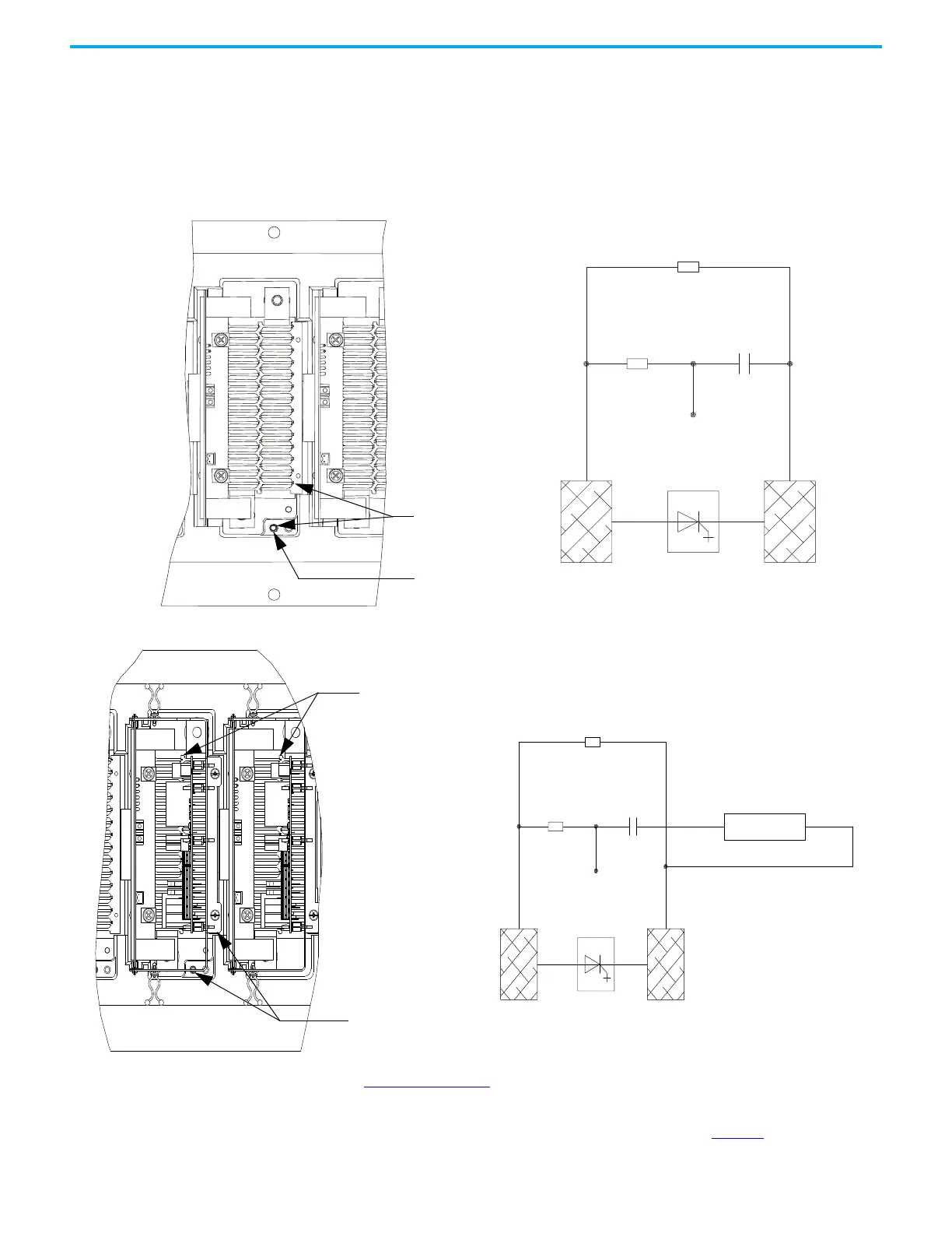
Snubber Resistance (SGCT Device)
Access to the snubber resistor is not required to test the resistance. The
snubber circuit test point is located within the PowerCage module under the
heatsinks. For each device, there is one test point. To verify the resistance,
measure the resistance between the test point and the heatsink above.
Figure 57 - Snubber Resistor Test
Figure 58 - Snubber Resistor Test (with SPS Board)
See Table 6 on page 64 to determine the appropriate snubber resistance value
for the current rating of the SGCT used.
If the resistor is found to be out of tolerance, see page page 72
for detailed
instructions on replacing the snubber resistor assembly.
Snubber test point
Measure resistance
between heatsink
and test point
Heatsink Heatsink
SGCT
Snubber
Resistor
Snubber
Capacitor
Sharing Resistor
Test Point
Resistance value between
heatsink and test point is
Snubber Resistance
Heatsink Heatsink
Snubber
Resistor
Snubber
Capacitor
Sharing Resistor
J1
SPS Board
1
2
SGCT
Test Point
Resistance Value between two
heatsinks is sharing resistance
in parallel with Anode-Cathode
Resistance

 Loading...


