Rockwell Automation Publication 7000-UM202H-EN-P - November 2023 157
Chapter 3 Control Component Definition and Maintenance
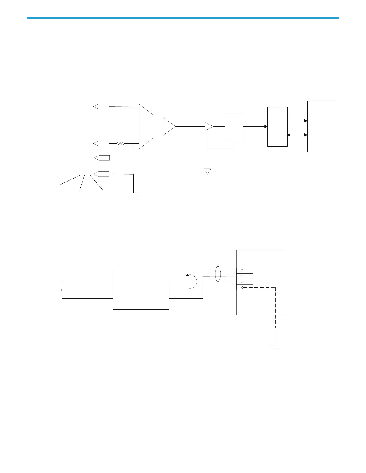
Isolated Process Receiver
These inputs are individually configurable to accept either a -10/0/+10V input
signal or a 4-20 mA signal. When configured for voltage input, each channel
has an input impedance of 75 K Ω. When used as a current loop input, the
transmitter must have a minimum loop compliance of 2V to satisfy the 100 Ω
input impedance. Regardless of input configuration, each input is individually
isolated to ± 100V DC or 70V RMS AC.
Figure 133 - Process Loop Receiver block diagram
The receiver can accept 4-wire transmitters. The figure below shows the
recommended connections. Again, the type of shielded cable used is
application specific as per the transmitter.
Figure 134 - Process Loop Receiver connections
+
Isolation Amplifier
FPGA
DSP
1, 5, 9
2, 6, 10
3, 7, 11
4, 8, 12
1st I/P Pins
2nd I/P Pins
3rd I/P Pins
VP
P
G
N
D
O
u
t
R
T
N
D
C
IFM
20
21
19
22
4-Wire Transmitter
User-supplied Power
(Sinking)

 Loading...


