14 Rockwell Automation Publication 7000-UM202H-EN-P - November 2023
Chapter 1 PowerFlex 7000 Drive Overview
Rectifier Designs Configurations
The PowerFlex 7000 drive offers three rectifier configurations for ‘B’ frame
drives:
• Direct-to-Drive™ (AFE rectifier with integral line reactor and CMC)
• AFE rectifier with separate isolation transformer
• 18-pulse rectifier with separate isolation transformer
Direct-to-Drive
Direct-to-Drive technology does not require an isolation transformer or
multiple rectifier bridges as in voltage source inverter (VSI) topologies offered
by others. The approach is completely different. Instead of multiple
uncontrolled rectifiers, a single AFE rectifier bridge is supplied. The rectifier
semiconductors that are used are SGCTs. Unlike the diodes that are used in
VSI rectifier bridges, SGCTs are turned on and off by a gating signal. A PWM
gating algorithm controls the firing of the rectifier devices, similar to the
control philosophy of the inverter. The gating algorithm uses a specific
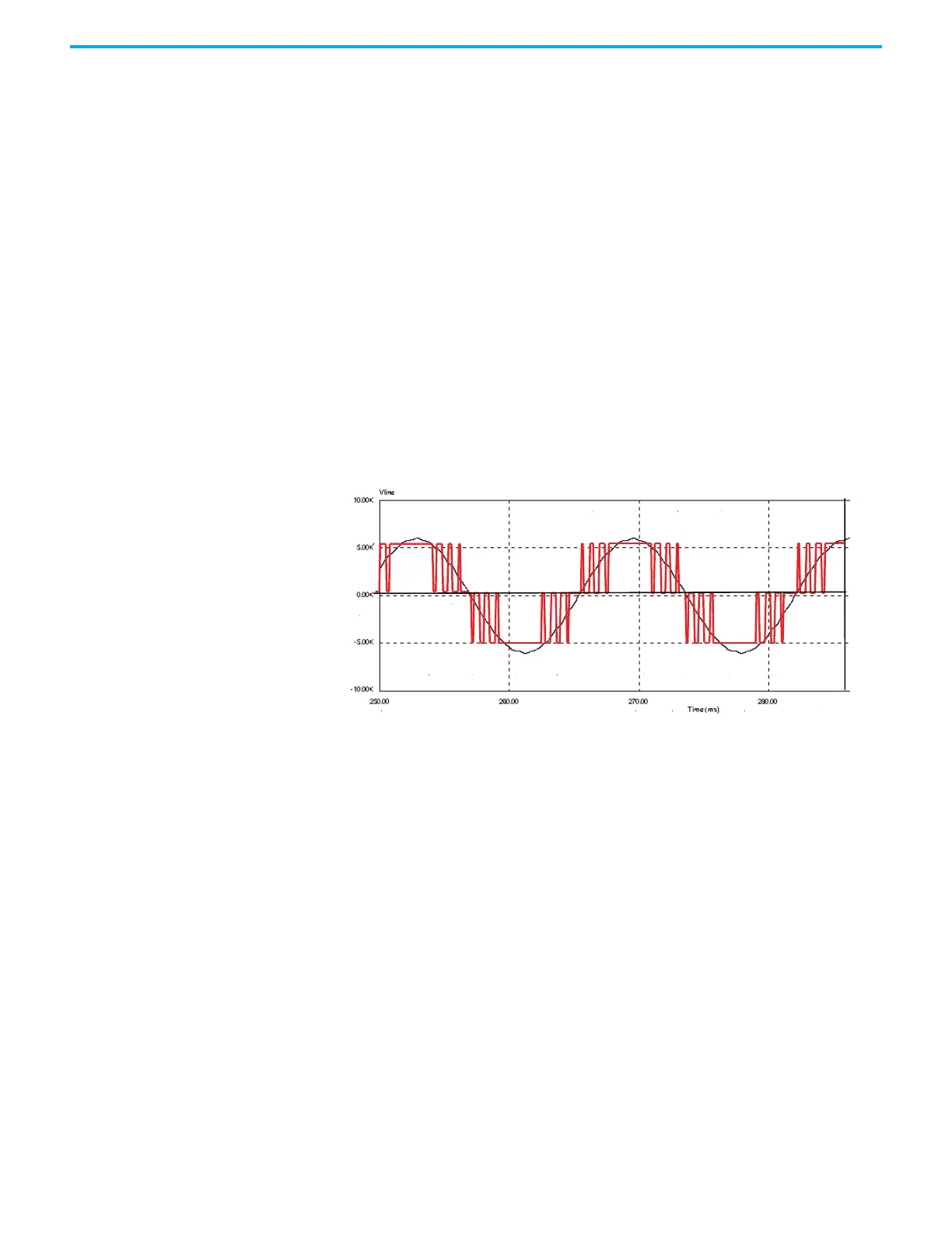
42-pulse switching pattern called selective harmonic elimination (SHE) to
mitigate the 5th, 7th, and 11th harmonic orders.
Figure 1 - Typical PWM Switching Pattern, Line Voltage Waveform
A small integral line reactor and capacitor addresses the high harmonic orders
(13th and above) and provides virtually sinusoidal input voltage and current
waveforms back to the distribution system. This configuration delivers
excellent line-side harmonic and power factor performance to meet IEEE 519-
1992 requirements and other global harmonic standards in virtually all cases.
This setup also provides a simple, robust power structure that maximizes
uptime by minimizing the number of discrete components and the number of
interconnections required.
A CMC mitigates the common mode voltage seen at the motor terminals, so
standard (non-inverter duty rated) motors and motor cables can be used. This
technology is ideal for retrofitting existing motor applications.

 Loading...


