64 Rockwell Automation Publication 7000-UM202H-EN-P - November 2023
Chapter 2 Power Component Definition and Maintenance
total reverse voltage blocking (PIV) capacity, as seen by the electrical circuit. A
single SGCT has a PIV rating of 6500V. This single device provides sufficient
design margin for electrical systems with 2400V medium voltage supply. At
4160V, connect two SGCTs in series to provide a net PIV of 13,000V to achieve
the necessary design margin. Similarly, connect three SGCTs in series at 6.6
kV, providing a net PIV of 19,500V to achieve the necessary design margin.
To meet the cooling requirements of the SGCT, place the SGCT between two
forced air-cooled heatsinks, one heatsink on the anode and the other heatsink
on the cathode. The force on the SGCTs differs with the size of the device. The
clamp assembly on the right hand side of the inverter module generates these
forces.
The SGCTs require uniform pressure to prevent damage and to ensure low
thermal resistance. Achieve uniform pressure by loosening the heatsink
mounting bolts, tightening the clamp, then tightening the heatsink bolts.
This design directs external filtered air through the heatsink slots to dissipate
heat from the SGCTs. The door filter is designed to keep the heatsink slots free
of dust particles.
SGCT Testing
The following sections outline how to verify SGCT semiconductors and all
associated snubber components. A quick reference to the expected resistance
and capacitance values as well as a simple schematic diagram is located in the
table below. A simple schematic diagram in Figure 43 on page 58
shows how
the snubber components are connected across an SGCT.
SGCT Anode-to-Cathode (Sharing) Resistance
The anode-cathode resistance check measures the parallel combination of the
sharing resistor and SGCT anode-cathode resistance. The sharing resistor has
a resistance much lower than that of a good SGCT, so the measurement will be
slightly less than the resistance of the sharing resistor. A measurement
between 60 kΩ and 75 kΩ indicates the SGCT is in good condition and that
wiring to the SGCT is correct. If the SGCT fails, it will be in the shorted mode, 0
Ω. The anode-to-cathode resistance check will be 0 Ω.
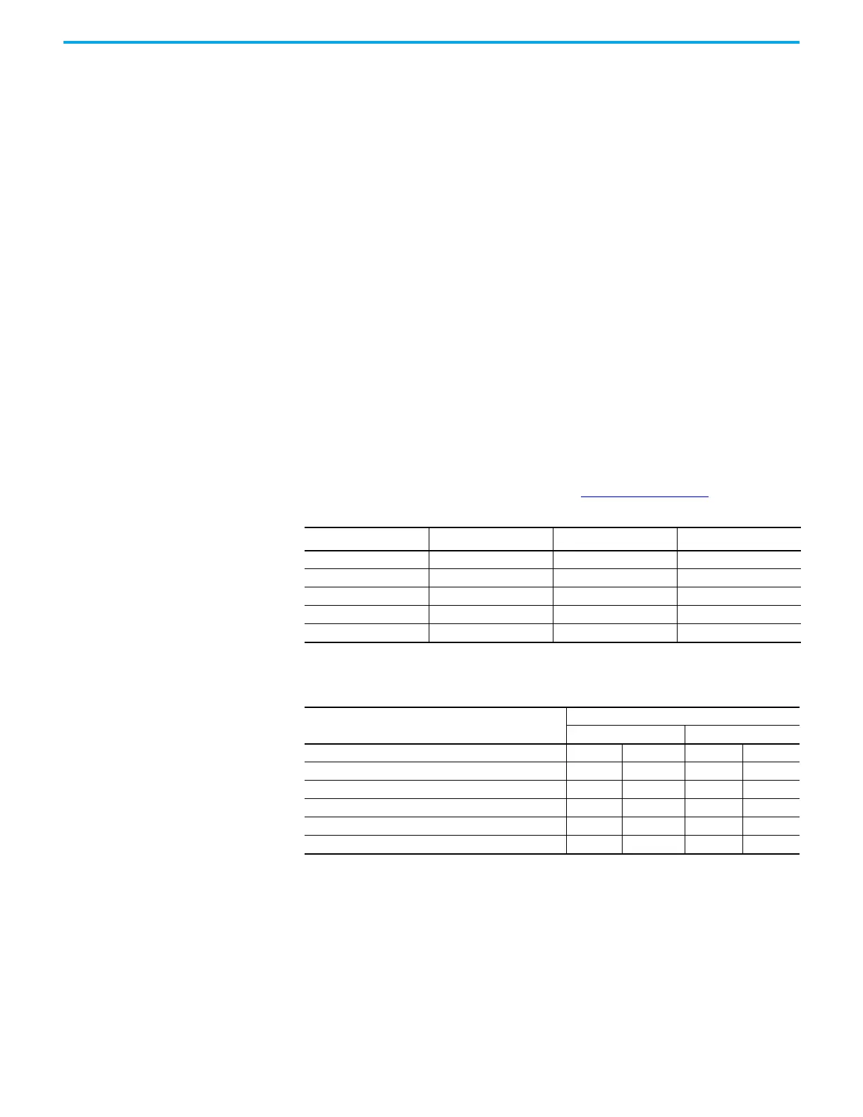
SGCT Rating
Sharing Resistor
(1)
(1) 2400V drives will not have a sharing resistor on devices.
Snubber Resistor Snubber Capacitor
1500 A 80 kΩ 6 Ω (AFE rectifier) 0.2 µf
1500 A 80 kΩ 7.5 Ω (Inverter) 0.2 µf
800 A 80 kΩ 10 Ω 0.1 µf
400 A 80 kΩ 15 Ω (AFE rectifier) 0.1 µf
400 A 80 kΩ 17.5 Ω (Inverter) 0.1 µf
Table 6 - SGCT/Snubber Resistance Values
SGCT Resistance Measurement
Measured Resistance
Inverter Rectifier (AFE only)
SGCT Anode-Cathode Resistance (heatsink to heatsink) k-Ω
(Lowest) (Highest) (Lowest) (Highest)
Snubber Resistance (Test point: heatsink above) Ω
(Lowest) (Highest) (Lowest) (Highest)
Snubber Capacitance (Test Point – heatsink on Right) µF
(Lowest) (Highest) (Lowest) (Highest)

 Loading...


