Rockwell Automation Publication 7000-UM202H-EN-P - November 2023 137
Chapter 3 Control Component Definition and Maintenance
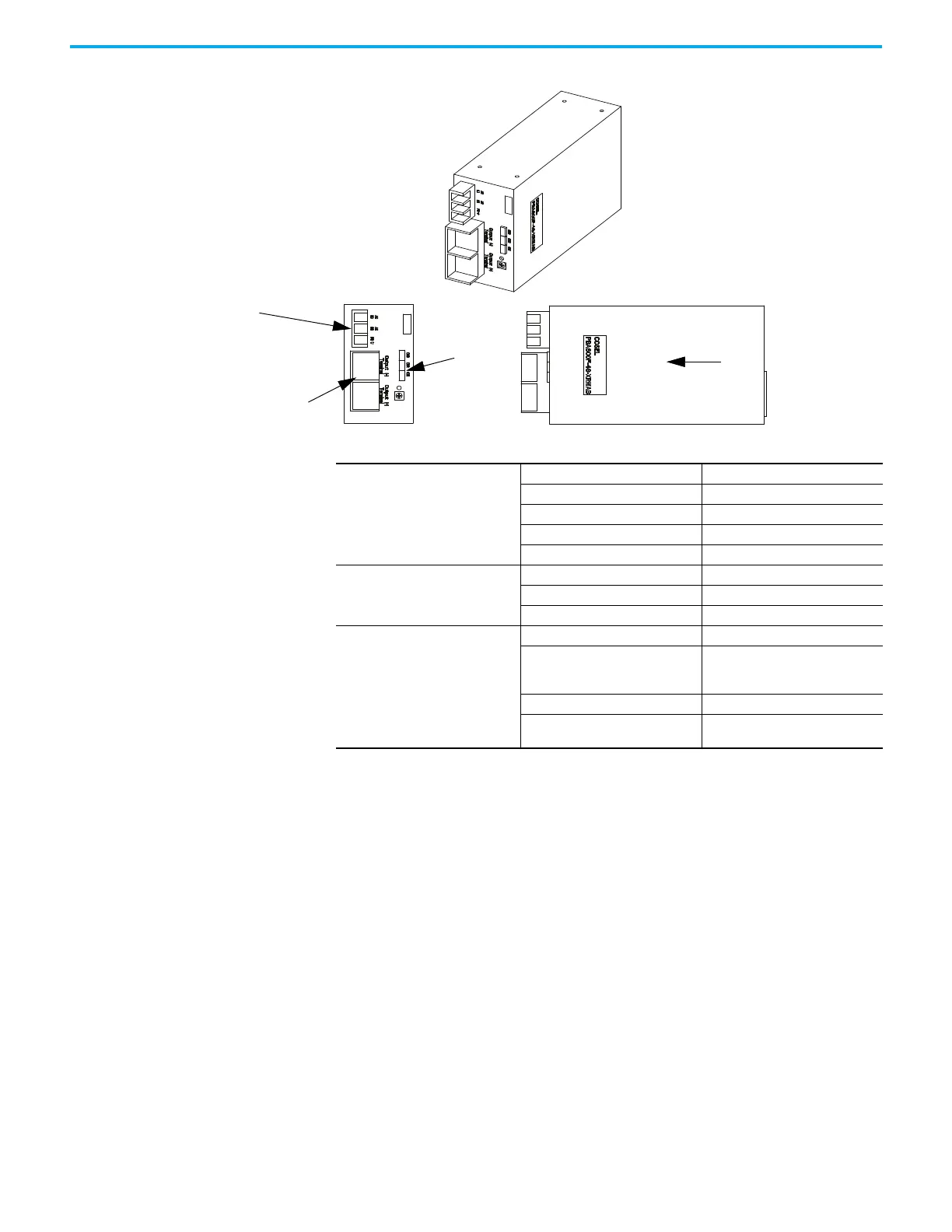
Figure 119 - Terminal Locations on 600W AC/DC Power Supply (Cosel)
Output Calibration
Ensure the output of the supply is 56V DC
(a)
.
There is a potentiometer on the top of the power supply that adjusts the
56V DC
(1)
output for the power supply. Isolate the output of the power supplies;
multiple supplies in series will affect your measurements. With the control
power on and the output of the AC/DC Converter isolated from the drive
control, adjust the potentiometer until the output equals 56V DC
(1)
. Perform
this test on each power supply. When all adjustments are complete, reconnect
the power supply to the circuit and re-measure the output. Readjust if
necessary.
If it is not possible to maintain 56V DC
(1)
, the power supply may be faulty.
Terminal/Connections
Descriptions
(600W Cosel Power Supply)
Single Phase Input
DC Outputs
Control Signals
Air Flow
FRONT VIEW
P1-AC Input
PIN# LABEL
AC (L) Live
AC (N) (1500 W only) Neutral (1500 W only)
NC No Connection
FG Earth
P2-DC Output
PIN# LABEL
++56V
–+56V COMM
P3-Fail Output
PIN# LABEL
CN1
1-2 Connected
3-4 Connected
5, 6, 7, 8, 9, 10 N/C
CN2 N/C
CN3
7 - Alarm
8 - Alarm GND
(a) 56V DC for Pioneer and Cosel model numbers -XRWAC and earlier. 57V DC for Cosel model numbers -XRWAD and newer.

 Loading...


