Rockwell Automation Publication 7000-UM202H-EN-P - November 2023 189
Appendix B PowerFlex 7000 Drive Spare Part Storage Requirements and Recommendations
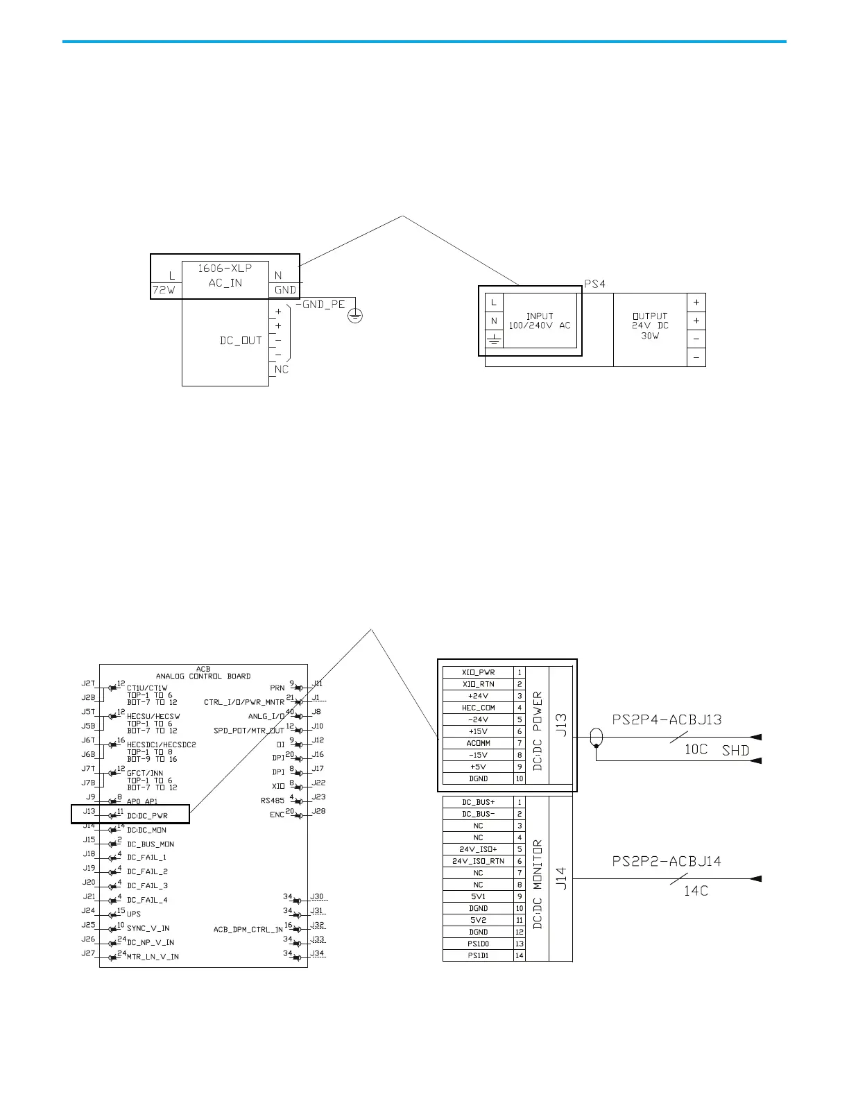
1606 Power Supply
1. Connect the variable AC source to the AC input terminals of 1606 power
supply via 2 circuit breaker.
2. Use 12 AWG (3.3 mm
2
) wire to connect the devices.
Figure 148 - 1606 Power Supply
Control Equipment and
Boards Connection
Guidelines
Analog Control Board (ACB)
1. Connect the variable DC source with current limiting function (5V DC/
200mA) to the +5V and DGND pin to the +5V pin of ACB DC input
connector J13.
2. Use 18 AWG (0.8 mm
2
) wire to connect the devices.
Figure 149 - Analog Control Board
AC Input Terminals
New Style Drawing
Old Style Drawing
AC Input Terminals
New Style Drawing
Old Style Drawing

 Loading...


