Rockwell Automation Publication 7000-UM202H-EN-P - November 2023 125
Chapter 2 Power Component Definition and Maintenance
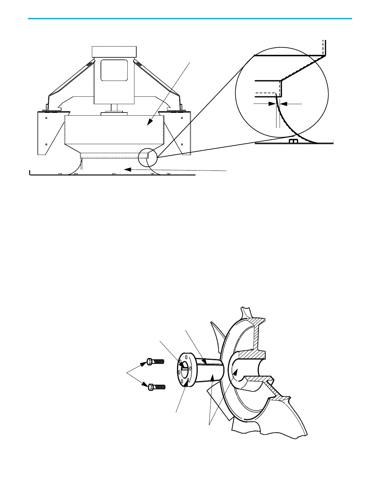
Figure 107 - Fan Assembly Installation
Impeller Maintenance
The fan impeller connects to the motor shaft with a split tapered bushing. This
bushing is positioned on the motor shaft and through the center of the
impeller. Two cap screws, when tightened to 10.2 N•m (7.5 lb•ft), lock the
bushing onto the motor shaft and the impeller to the bushing.
Impeller Removal from Motor Shaft
The impeller is not designed to support the weight of the motor.
If vertical, the impeller and bushing may fall when loosening cap screws.
Physical injury or component damage may result.
Figure 108 - Impeller Removal
1. Record the distance from the end of the motor shaft to the bushing. The
new impeller must be installed in the same location. Failure to do so will
Outer Fan Shroud
Inlet Ring
Gap MUST
be 6.3 mm
(0.25 in.) on
both sides
Cap Screws
Threaded Hole for
Separating Tapers
Key
Split in Taper Bushing
Taper Surfaces

 Loading...


