Rockwell Automation Publication 7000-UM202H-EN-P - November 2023 113
Chapter 2 Power Component Definition and Maintenance
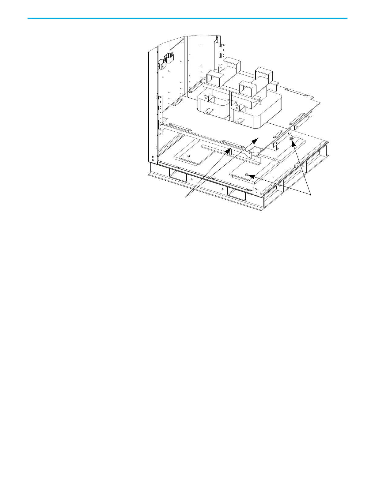
Figure 102 - DC Link Removal (Heatpipe Model)
Install the replacement DC link in the reverse order of its removal.
DC link leads or cable must be routed so that electrical clearances are
maintained and the correct terminals are connected. You must also verify that
the nameplate ratings are the same or appropriate for the drive system. A
different DC link will require different parameter settings.
The DC link maintains a low ripple current between the line converter and the
machine converter. Thermal protection of the DC link reactor is provided by
two normally closed contacts wired to the I/O module. These contacts will open
at 190°C and cause a fault/alarm message to be displayed.
The DC link in a heatpipe cabinet has a large medium voltage door.
Interlocking prevents opening the medium voltage door unless the source
power is locked out.
Fan power must be disconnected using the handle on the right hand side of the
LV door to open the LV compartment.
3. Remove DC
Link hardware
and slide DC Link
forward
1. Remove front DC Link
barrier and front barrier
support brace

 Loading...


