160 Rockwell Automation Publication 7000-UM202H-EN-P - November 2023
Chapter 3 Control Component Definition and Maintenance
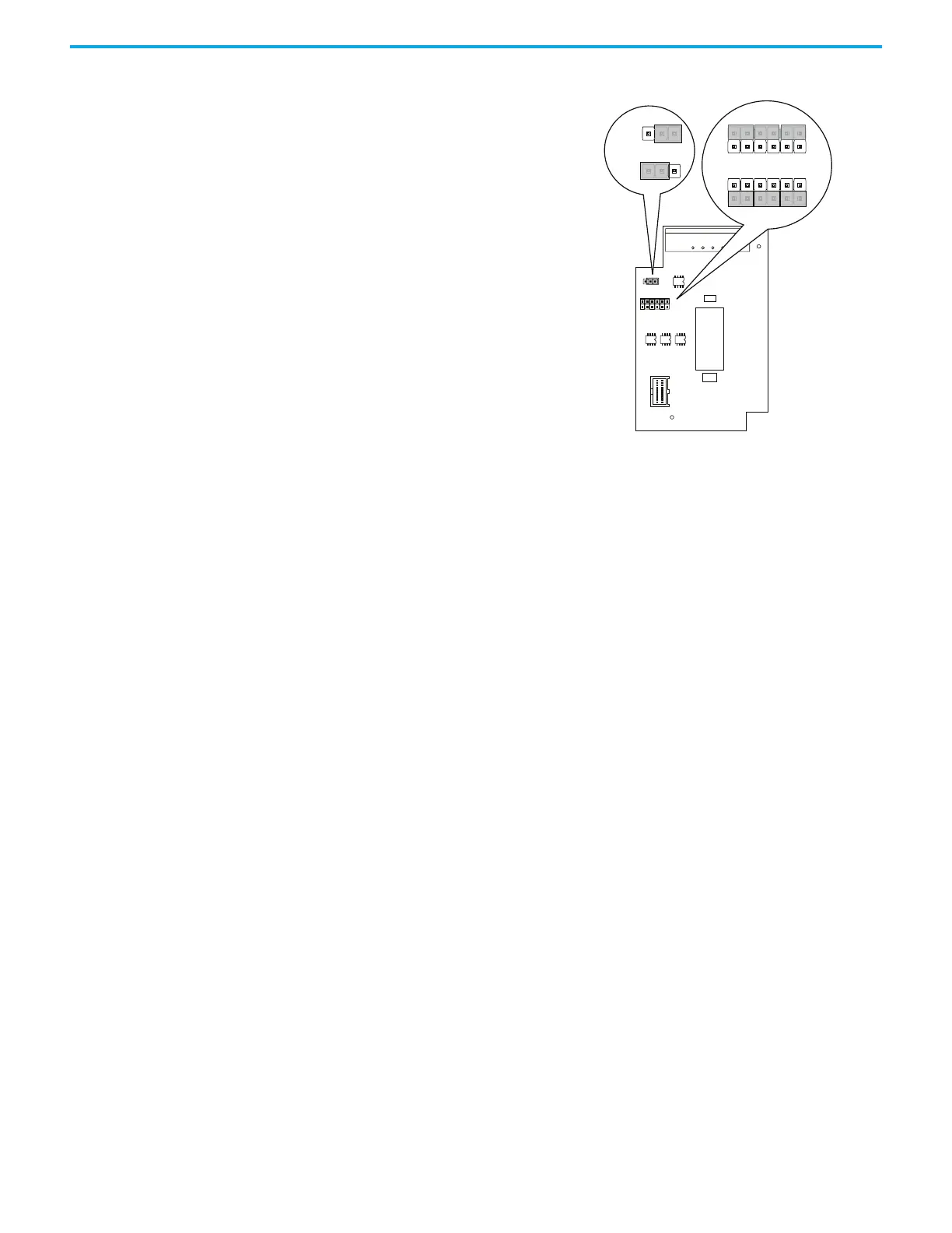
Figure 136 - 20B-ENC-3 Encoder Interface
Operation at 5V does not support long cable lengths, given the need to regulate
power within 5% at the encoder. Cable resistance and capacitance makes it
difficult to regulate power at the encoder to 4.75V. Longer cables may decrease
voltage below 4.75V, causing encoder malfunction. As a general rule, using 18
Avg cabling with an Rdc of 19.3 Ω/km limits the cable length to 12 m (42 ft)
from the board to the encoder.
Input Connections
All encoder interface connections occur at J1, as follows.
• J1 Pin 1 A+
• J1 Pin 2 A-
•J1 Pin 3 B+
•J1 Pin 4 B-
•J1 Pin 5 Z+
•J1 Pin 6 Z-
• J1 Pin 7 encoder power return
• J1 Pin 8 encoder power (+12V @ 3 W)
80190-759-01, 80190-759-02 Universal Encoder Interface
The universal encoder interface enables connections between the drive and to
an absolute position encoder or a standard quadrature encoder, providing the
option for dual or redundant quadrature encoders. The universal encoder
interface provides 12 single ended or 6 differential, optically isolated inputs as
well as a 12V/3W galvanically isolated encoder power source.
When using absolute encoders, use the 12 single ended inputs. For quadrature
encoders, use the six differential inputs.
Either encoder with frequencies up to 200 kHz connects to the universal
encoder interface.
J3
J3
J2
+12V
1
2
3
12 11
21
+5VR EF
1
2
3
+5V
+12V
1
2
3
+12V
+5V
12 11
21
12 11
21
J2
NOTE: Must be configured for 12V
operation
Output
Config.
Input
Config.