Rockwell Automation Publication 7000-UM202H-EN-P - November 2023 169
Chapter 3 Control Component Definition and Maintenance
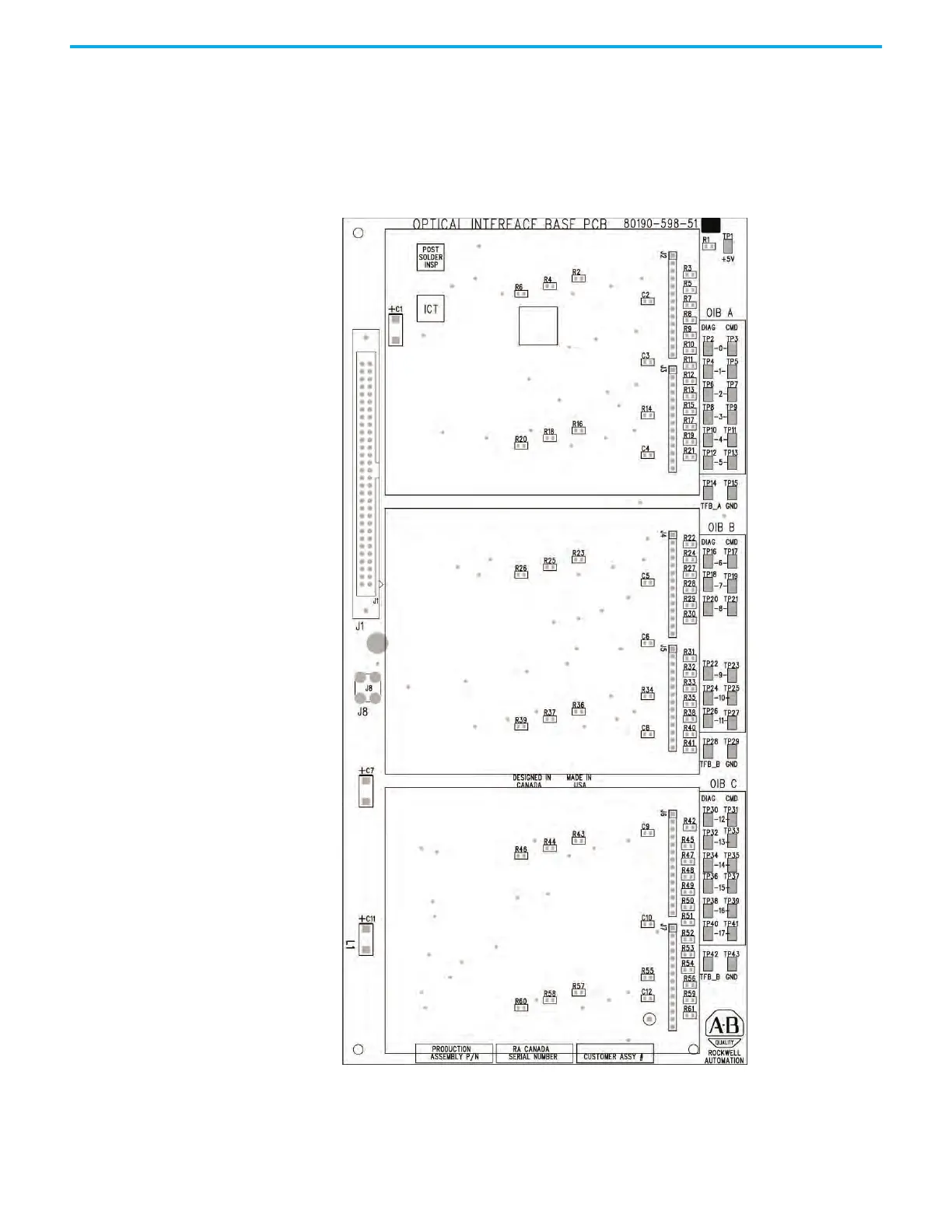
This board provides the mechanical and electrical interconnections between
the OIBs and the DPM. The board connects to either J11 or J12 on the DPM via a
60-conductor shielded-ribbon cable. Attach the cable drain wire to the screw
terminal J8. The remaining connectors on the board complete the electrical
connection of the installed OIBs to the DPM. Each OIB can support from one
to three OIBs.
Figure 142 - Optical Interface Base Board (OIBB)

 Loading...


