94 Rockwell Automation Publication 7000-UM202H-EN-P - November 2023
Chapter 2 Power Component Definition and Maintenance
12. Replace front white heatpipe retaining bracket.
13. Replace top heatsink horizontal fin support.
14. Replace the snubber resistor wire lugged connection and thermistor
connection, if present.
15. Replace the SGCT as described in Replacing the SGCT
on page 69.
16. Re-apply clamp force to heatpipes:
a. Apply a thin layer of electrical joint compound (Alcoa EJC No.2 or
approved equivalent) to the clamp head pressure pad face.
b. Tighten the clamp to the proper force until you can turn the indicating
washers by the fingers with some resistance.
17. Once clamp force has been re-applied, tighten heatpipe locking nuts on
top of horizontal fin support (center nut at each sink) to 8 N•m
(6 lb•ft).
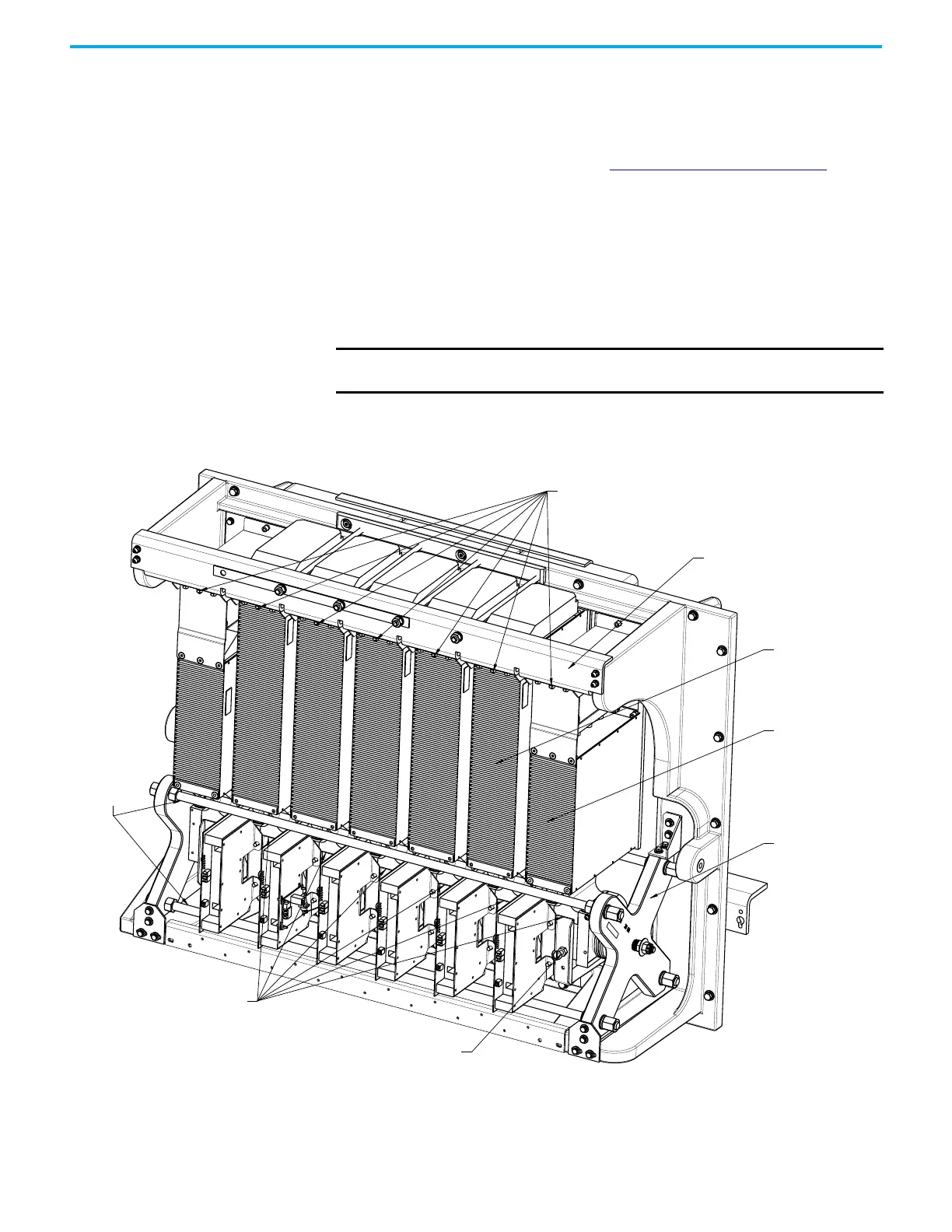
Figure 85 - Heatpipe PowerCage Module
IMPORTANT Do not re-tighten nylon shipping bolts on 6600V drives. They are for
shipping purposes only.
Heatpipe locking nuts
Horizontal Fin Support
Clamp Head
Glass Rods
Clamp
Head
White Heatpipe
Retaining Bracket
Nylon Shipping Bolt
Heatpipe
End Position
Heatpipe

 Loading...


