Troubleshooting the TX-I/O Island Bus
Technical Reference Manual
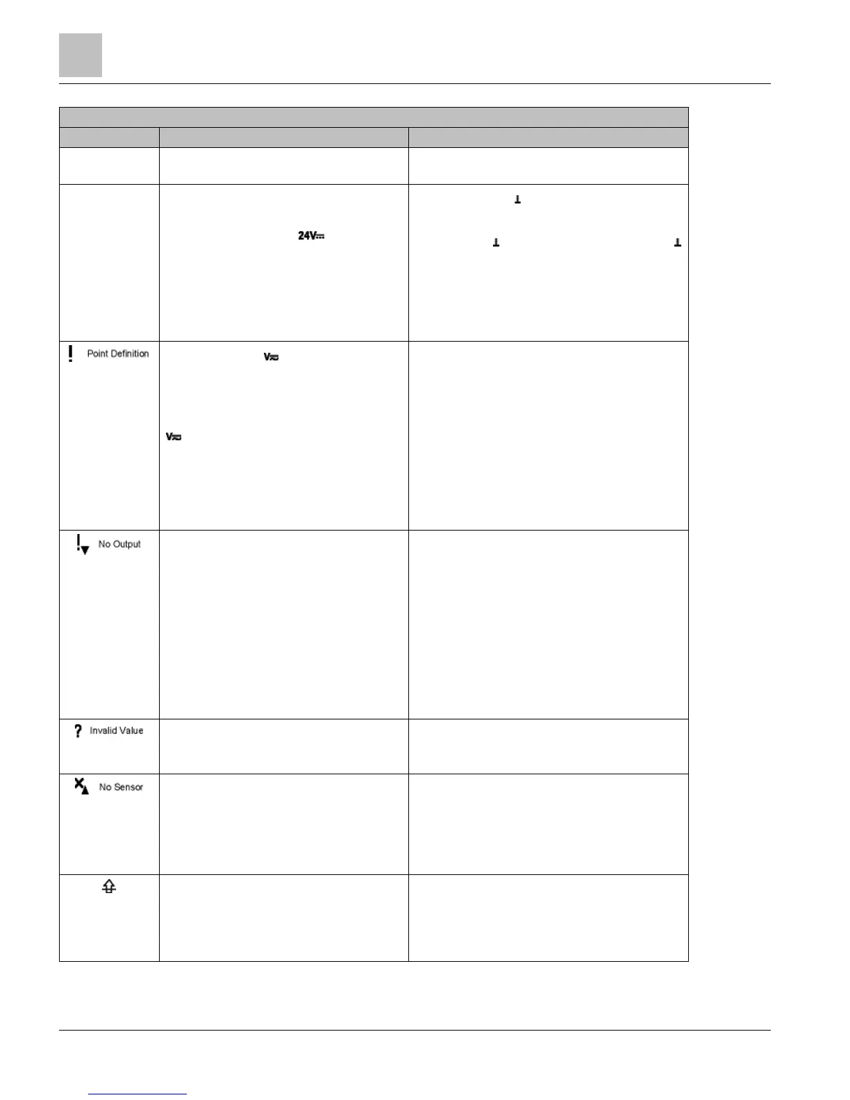
Incorrect point
type
The point type displayed does not correspond to
the point type defined in the database.
Using the job drawing or field panel layout sheet, verify
that the address keys are in the correct module.
Display is OFF
or
Display is ON, but
communications
are failed
Insufficient DC power.
also check
TX-I/O Power Supply LED ( ) is bright green.
Ensure CS and are connected to the Bus
Connection Module (BCM).
Ensure CS/ at the BCM is within 0.5 Vdc of CS/
at the Power Supply.
– The wire length may have attenuated the DC
power.
– Ensure the module diagnostics report is
normal.
Field device supply ( ) is missing or very low.
also check
The field device supply LED on the TX-I/O
Power Supply (24V~) or Bus Connection Module
( ) are bright green.
● Is a TX-
I/O module connected to the wrong side of
the Power Supply or Bus Connection Module?
The TX-I/O island bus must extend from the male
bus connector of the Power Supply or Bus
Connection Module.
● Is the field device supply LED OFF? If so:
– The 4A replaceable fuse may be blown.
– The field device supply may be off.
– Wires may be disconnected.
● Is the field device supply LED dimly lit?
– The field device supply may be too low.
Point is configured as an output signal and no
field device supply is available.
● Is a TX-
I/O module connected to the wrong side of
the Power Supply or Bus Connection Module?
The TX-I/O island bus must extend from the male
bus connector of the Power Supply or Bus
Connection Module.
● Is the field device supply LED OFF? If so:
– The 4A replaceable fuse may be blown.
– The field device supply may be off.
– Wires may be disconnected.
● Is the field device supply LED dimly lit?
– The field device supply may be too low.
Invalid process value (current output) ● Ensure the output current loop is intact.
● The ? symbol has higher priority than the !
symbol.
No sensor (current input)
● Ensure the sensor power wire is landed on the
sensor power terminals of an 8X module (3, 11,
20, or 28) and not on field device supply terminals
(7, 15, 24, or 32) of 8U or 8X modules.
● Verify the external wire at the sensor.
● An internal sensor wire may have a break.
Value above range limit
● NTC resistance is too low (temperature over
range).
● RTD resistance is too high (temperature over
range).
● The voltage or current input is too high.
 Loading...