HRX-OM-X010
Chapter 3 Transporting and Installation
3.3 Procedure for Installation HRZ Series
3.3.4 Wiring installation
Power cable
The power cables are to be prepared under your responsibility, referring to the
following table.
Table 3-1 Power Cable and Main Breaker (This System)
Communication connector
The communication connectors are to be prepared under your responsibility,
referring to the following table.
Table 3-2 Communication Connector
Contact signal (P1 connector)
Serial RS-485 (P2 connector)
HRZ002-WS-F
HRZ002-W1S-F
HRZ002-W2S-F
HRZ004-WS-F
HRZ004-W1S-F
HRZ004-W2S-F
HRZ008-WS-F
HRZ008-W1S-F
HRZ008-W2S-F
HRZ010-WS-F
HRZ010-W1S-F
HRZ010-W2S-F
Crimp contact
(recommended)
Main breaker (This System)
Only designated personnel are allowed to install wiring.
Be sure to turn OFF the power prior to wiring to assure safety.
Do not do any wiring when the system is energized.
The system wiring requires not only a thorough connection with the designated
cable but also securing to prevent loose connection. Poor connection and
securing may cause electric shock, heat sports, fire or communication errors.
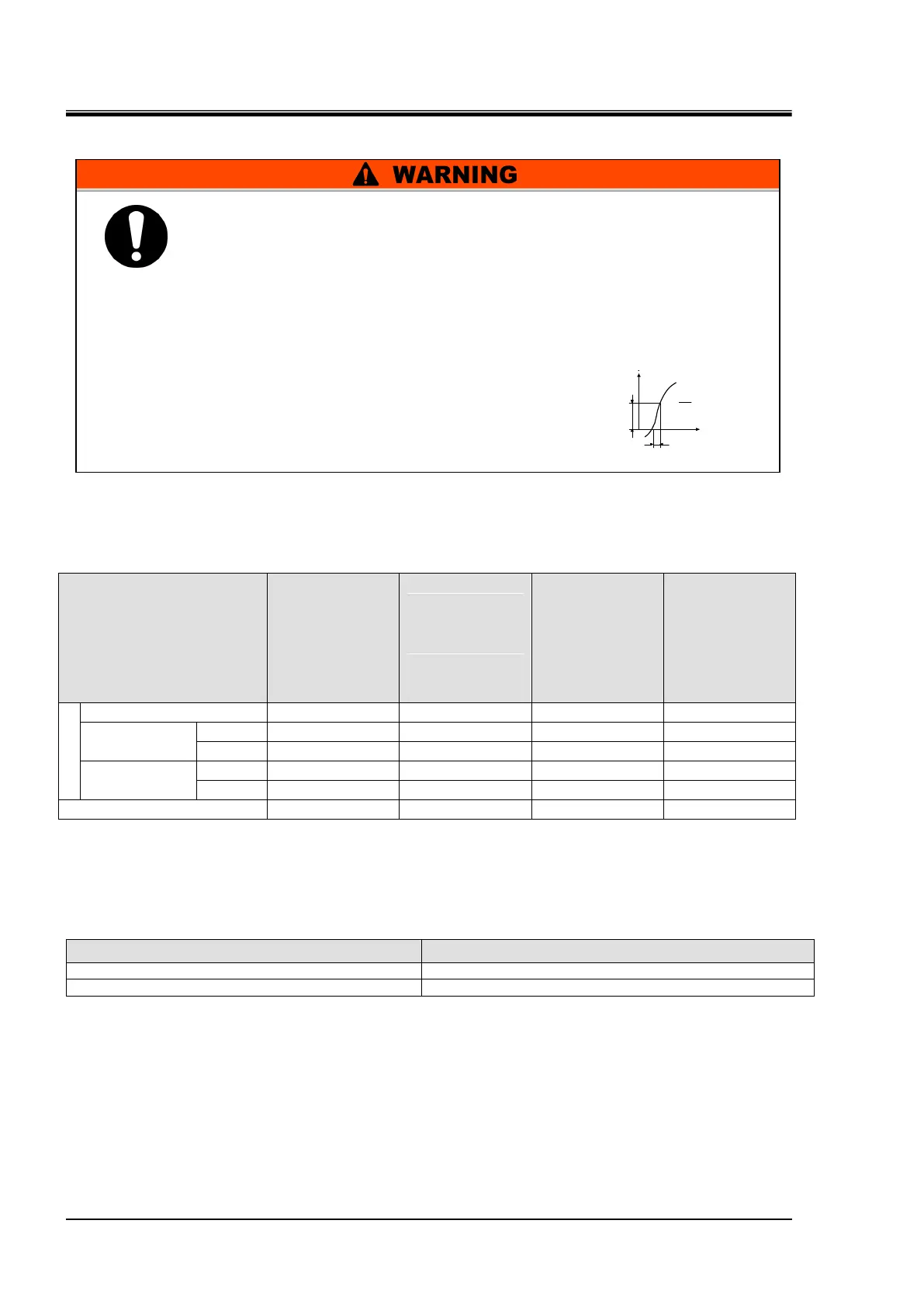
Be sure to supply the power to this system according to specifications.
Supply pure AC power. Potential malfunction may occur if a rectified AC with
voltage rise (dv/dt)
at zero crossing exceeds 40V /200µ sec.
Always establish a connection to a ground for safety.
Be sure that no ground connection is made to
a water pipe, gas pipe and lighting rod.
= Voltage ratio
on zero-cross point
 Loading...