HRX-OM-X010
Chapter 5 System Operation
5.3 Operation Screen HRZ Series
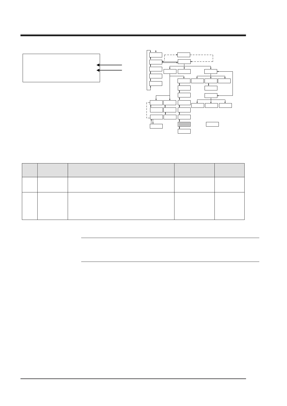
<INITIAL SET> ↕
OUT: N/A
E_OUT: N/A
5.3.22 Initial Setting screen 7
Figure 5-25 Initial Setting screen 7
Table 5-22 Initial Setting screen 7
Allows the selection of alarm signals for contact
signal.(See”Chapter 8 8.1.4 Alarm signal
selection“(P8-10) for details.)
Allows the selection of EVENT Output. Allows the
setting of content of output for pin No. 8 of “Chapter 8
8.1.3Communication specification Table
8.7Compliance“(pege 8-7).
See communication specification for details.
N/A
TEMP READY
*1
AUTO PURGE
[Tips]
See ”Chapter 8 8.5BAND/READY function“(page 8-17) for TEMP BAND, READY TIME (*1).
[▲] or [▼] key is used for selecting “Item” and move to other Initial Setting screens.
And pressing the [ENT] key enabling to select the setting or set value.
 Loading...