HRX-OM-X010
Chapter 8 Appendix
HRZ Series 8.1 Specification
Chapter 8 Appendix
8.1 Specification
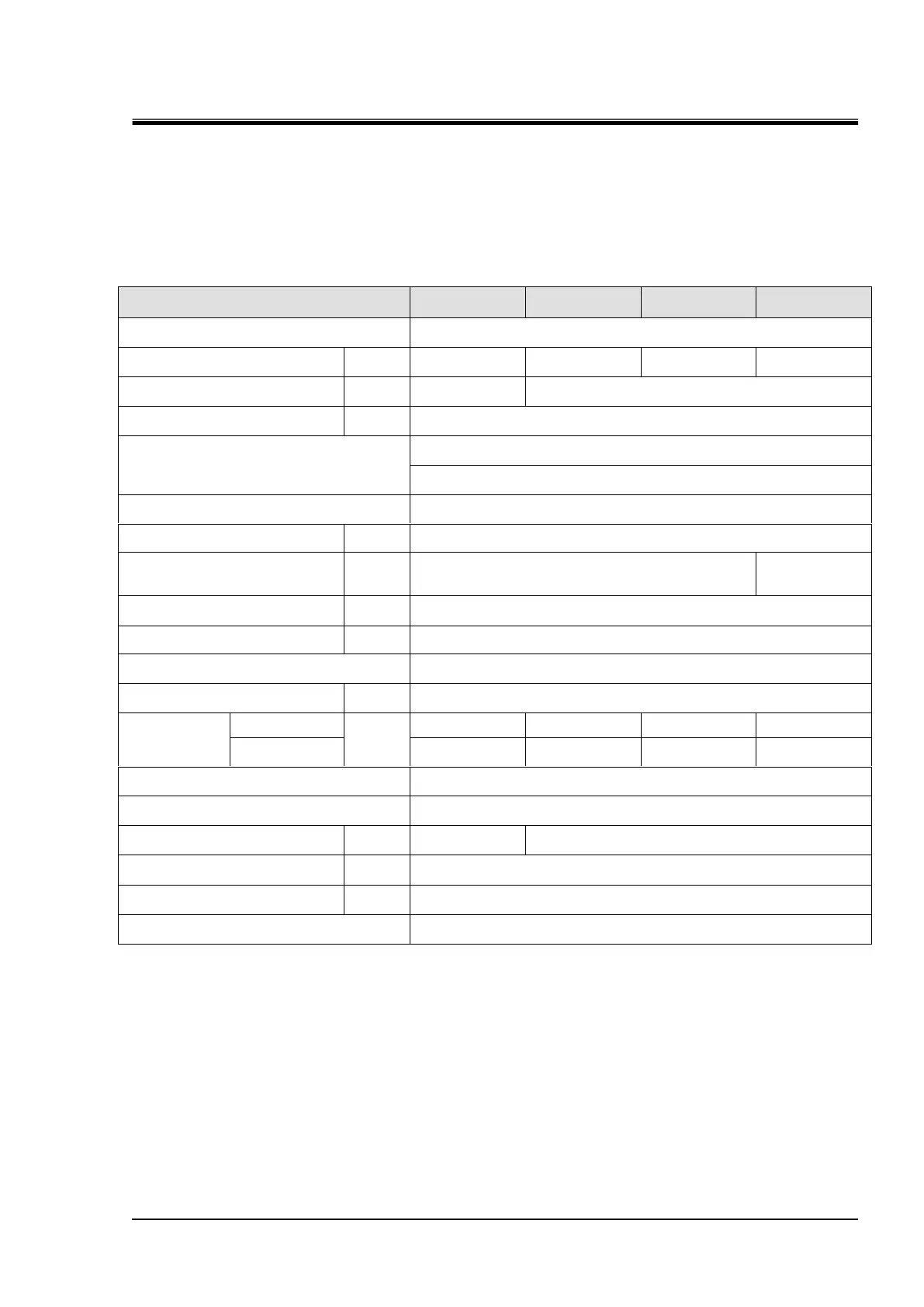
8.1.1 System specification
Specification for fluorinated fluid (wide temperature)
Table 8-1 Specification for Fluorinated Fluid (wide temperature)
Cooling capacity
*1
(50Hz/60Hz)
Operating temperature range
Galden
®
HT135
*3
Fluorinert
TM
FC-3283
*3
(-20 to 40 deg C)
Galden
®
HT200
*3
Fluorinert
TM
FC-40
*3
(20 to 90 deg C)
(No intrusion of foreign body)
0.65 (At 20L/min)
(94[PSIG] At 5.3 [gal/min])
0.72 (At 20L/min)
(104[PSIG] At 5.3
[gal/min])
10 to 30 / 0.3 to 0.7 (45 to 100 [PSIG])
Facility water
required flow rate
Temp. changing
condition
*10
3-phase 50/60Hz AC200/200 to 208V±10%
W380D870H950
(W14.96xD34.25xH37.40[inch])
Serial RS-485 (Dsub-9pin) , Contact signal (Dsub-25pin)
*1: The capacity is derived under the conditions that the circulating fluid temp is 20 deg C, the facility water temp. is 25 deg C and that
the circulating fluid flow rate is obtained at a specified flow rate of pump capacity.
*2: This is a system output temperature, with flow rate defined in pump capacity secured, when stabilized with no disturbance. Its
upper limit may be violated if an insufficient amount of the circulating fluid is present or a disturbance to flow rate is observed.
*3: Galden
®
is a registered trademark of Solvay Solexis, and Fluorinert
TM
is a trademark of U.S. 3M.
*4: The capacity is derived at the Outlet of this system when the circulating fluid temp. is at 20 deg C and maximum frequency
operation by inverter.
*5: This is a minimum amount of the fluid for operation of the Thermo Chiller outfitted with internal piping and heat exchanger in this
system. Circulating fluid temp.: 20deg C
*6: This is an auxiliary space with a main tank capacity excluded. Available for circulating fluid recovery from external piping and
backup supply.
*7: This is the dimensions of panels, which is derived without protrusions such as a breaker handle.
*8: This is the mass of the system when it contains no circulating fluid.
*9: The required flow rate when the cooling capacity load is applied under the condition in *1.
*10:Temporarily required flow rate when set temperature is changed under the facility water temp.25 deg C.
*11: The value of IPCC (Intergovernmental Panel on Climate Change) Forth Assignment Report : Climate Change 2007 (AR4).
 Loading...