HRX-OM-X010
Chapter 8 Appendix
8.1 Specification HRZ Series
Contact signal
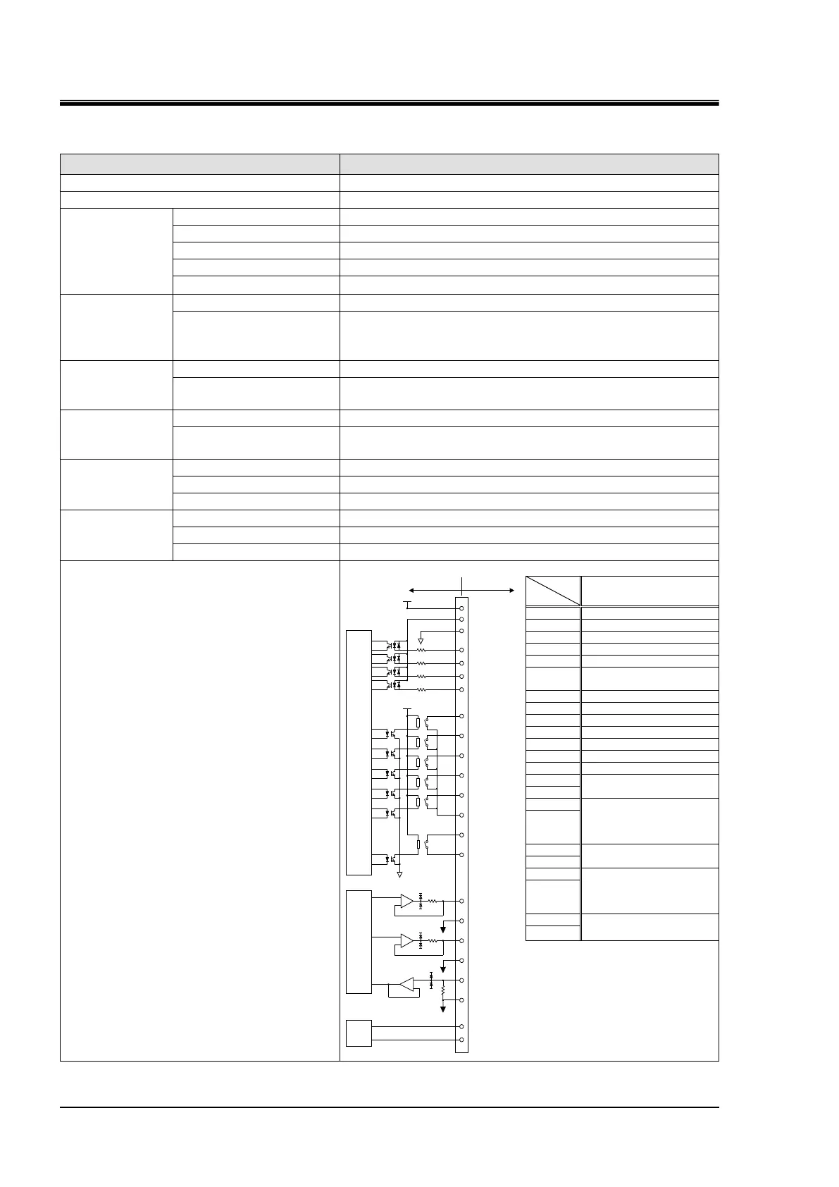
Table 8-7 Contact Signal
Connector type (this system)
D-sub25P female connector(M2.6x0.45)
Contact output
signal
(Other than Pin
No. 5-18)
Max. AC/DC 800mA
(Pin No. 15 is common to output signals. Total used load
current should be at or below 800mA)
Contact output
signal
(Pin No. 5-18)
AC/DC 800mA (resistance load)
Contact output
signal
(EMO signal)
AC/DC 800mA (resistance load, inductive load)
The product
DIGITAL
CIRCUIT
DC24V
+
-
-15V
100Ω
ANALOG COM
4.7kΩ
24COM
1
24COM
4.7kΩ
4.7kΩ
4.7kΩ
+15V
+
-
-15V
100Ω
+15V
ANALOG COM
+
-
-15V
+15V
ANALOG COM
ANALOG
CIRCUIT
14
3
16
4
17
6
19
7
20
8
15
5
18
11
23
10
22
12
24
13
25
1MΩ
EMO
CIRCUIT
2
DC24V
Pin number
Your system
DIO REMOTE signal 1
Recovery signal
*1
Temp.PV Analog
Output*2
[-100 to 100deg C:-10 to
10V]
DI PV Analog Output*3
[0 to 20 MΩ:0 to 10V]
Temp.SP Analog
Input*3
[-100 to 100 deg C:-10 to
10V]
*1: The recovery signal can be input only
when the circulating fluid automatic
collection function (optional) is used, and it
does not serve as the DIO REMOTE
signal.
*2 :Valid if Analog Communication (optional) is
provided.
*3 :Valid if DI Control Kit (optional) is provided.
 Loading...