5-25
7. V-COM Level Adjustment (PD-98 board)
Set the common electrode drive signal level of LCD to the specified
value.
Mode VTR playback
Signal Alignment tape:
For audio operation check
(XH5-3 (NTSC))
(XH5-3P (PAL))
Measurement Point Pin 4 of CN5501 (PANEL COM)
Measuring Instrument Oscilloscope
Adjustment Page D
Adjustment Address 64
Specified Value A = 4.95 ± 0.05V (NTSC)
A = 4.95 ± 0.05V (PAL)
Note: Perform “Bright Adjustment” and “Contrast Adjustment” before this
adjustment.
Adjusting method:
1) Select page: 0, address: 01, and set data: 01.
2) Select page: D, address: 64, change the data and set the PANEL
COM signal level (A) to the specified value.
3) Press the PAUSE button of the adjusting remote commander.
4) Select page: 0, address: 01, and set data: 00.
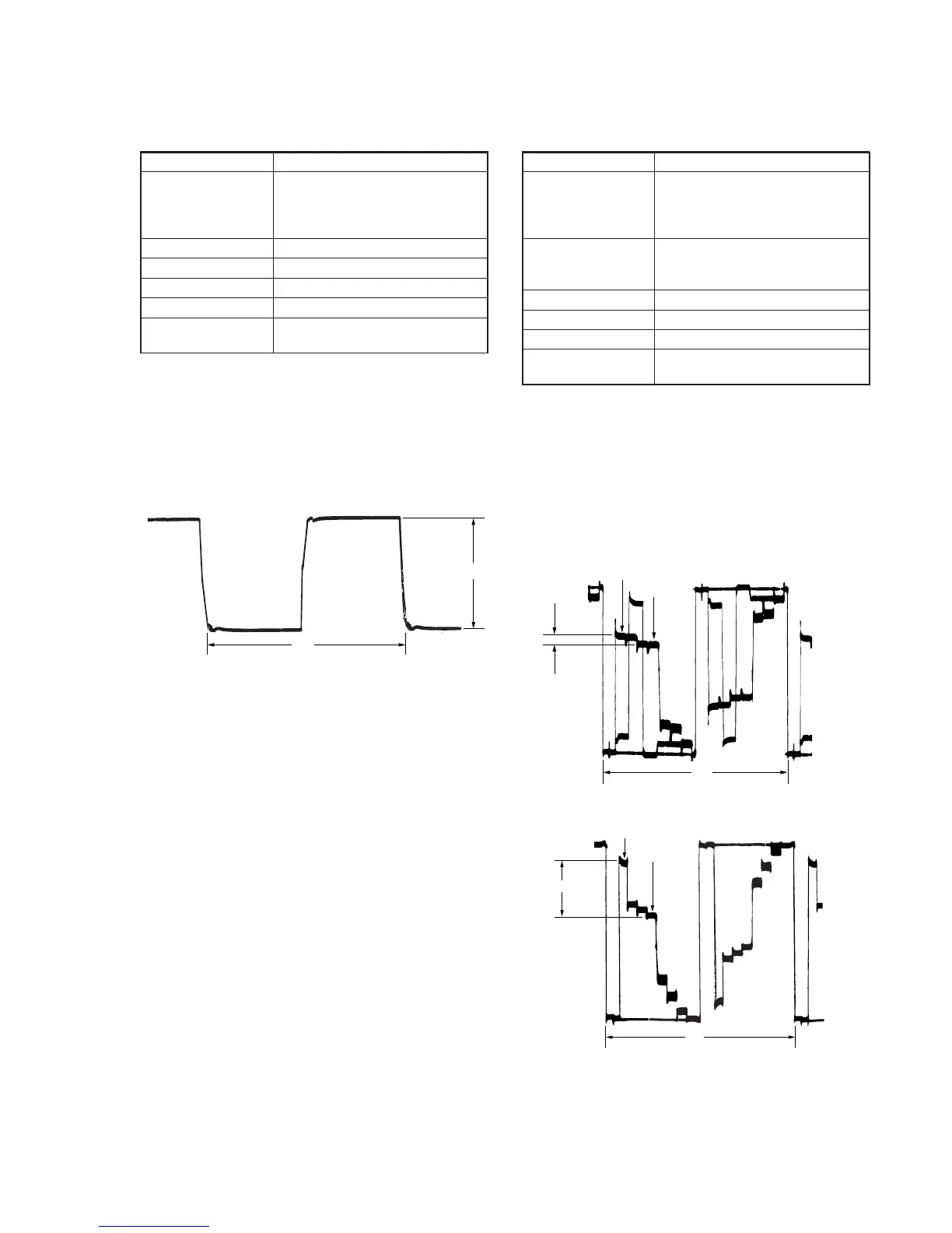
Fig. 5-1-20
A
2H
8. Color Adjustment (PD-98 board)
Set the color saturation to the standard value. If deviated, the color
will be to dark or light.
Mode VTR playback
Signal Alignment tape:
For audio operation check
(XH5-3 (NTSC))
(XH5-3P (PAL))
Measurement Point Pin 2 of CN5501 (VG)
External trigger : Pin 4 of CN5501
(PANEL COM)
Measuring Instrument Oscilloscope
Adjustment Page D
Adjustment Address 6D
Specified Value A = 0.15 ± 0.05V (NTSC)
A = 0.99 ± 0.05V (PAL)
Adjusting method:
1) Select page: 0, address: 01, and set data: 01.
2) Select page: 2, address: 1F, set data: 02.
3) Select page: D, address: 6D, change the data and set the voltage
(A) between the white and green to the specified value.
4) Press the PAUSE button of the adjusting remote commander.
5) Select page: 2, address: 1F, set data: 00.
6) Select page: 0, address: 01, and set data: 00.
For NTSC model
For PAL model
Fig. 5-1-21
White (75 )
Green
A
2H
White (100 )
Green
2H
A
 Loading...


