5-57
3-5. IR TRANSMITTER ADJUSTMENTS
(Except DCR-TRV9E AEP/UK model)
Adjust using a IR receiver jig (J-6082-383-A).
Switch setting:
LASER LINK ................................................ ON (Red LED is lit)
1. IR Video Carrier Frequency Adjustment
(MA-322 board)
Mode Camera standby
Subject Arbitrary
Measurement Point Pin 5 of CN003 of IR receiver jig
(RF) (Or Pin !§ of IC8401)
Measuring Instrument Frequency counter
Adjustment Page D
Adjustment Address 90
Specified Value f = 11.85 ± 0.05 MHz
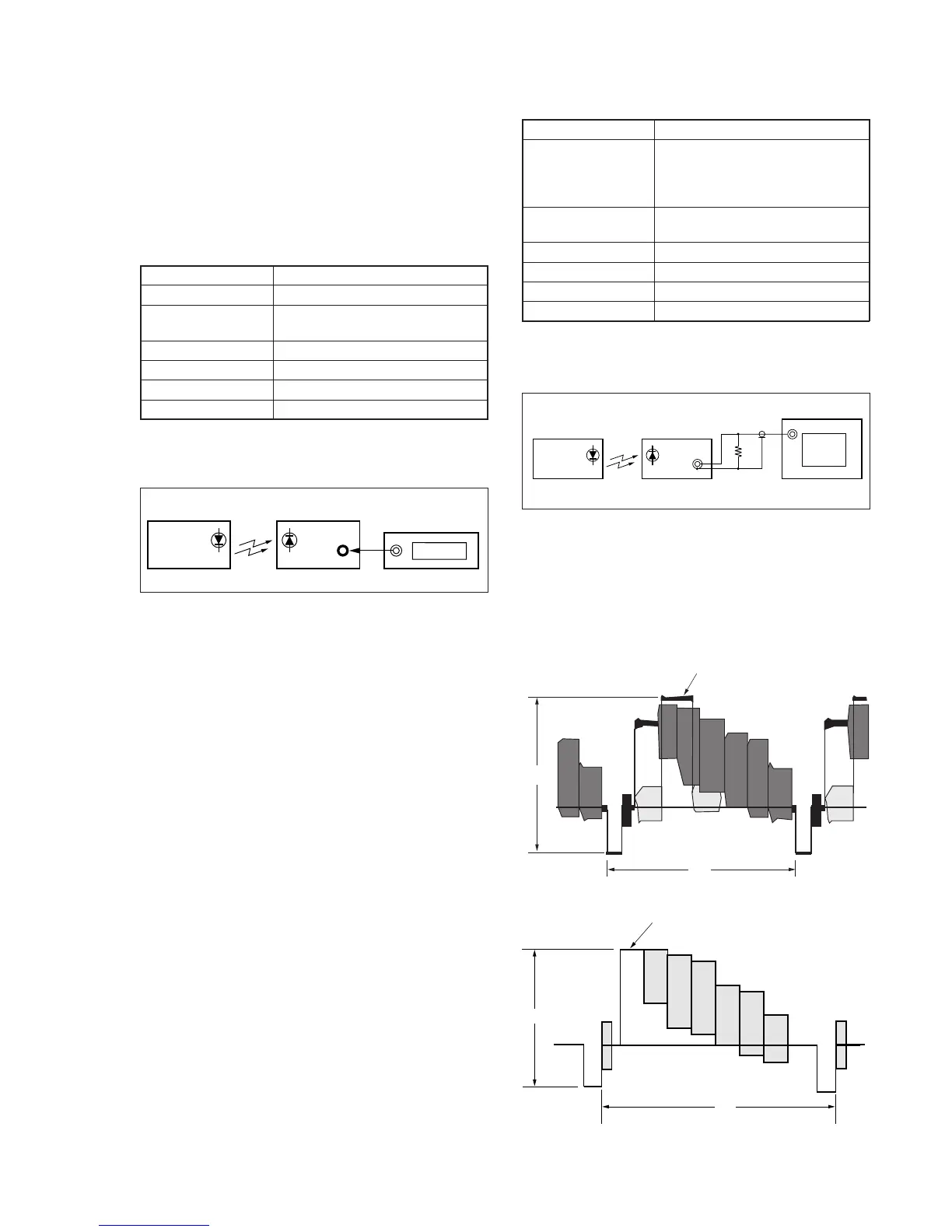
Connection of Equipment
Connect the measuring device as shown in the following figure,
and adjust.
Fig. 5-3-18
Adjusting method:
1) Select page: 0, address: 01, and set data: 01.
2) Select page: 2, address: 12, set data: 10, and press the PAUSE
button of the adjusting remote commander.
3) Select page: D, address: 90, change the data, and set the video
carrier frequency (f) to the specified value.
4) Press the PAUSE button of the adjusting remote commander.
5) Select page: 2, address: 12, set data: 00, and press the PAUSE
button of the adjusting remote commander.
6) Select page: 0, address: 01, and set data: 00.
Main unit
IR receiver jig
CN003
pin
5
Frequency counter
2. IR Video Deviation Adjustment (MA-322 board)
Mode VTR playback
Signal Alignment tape:
For audio operation check
(XH5-3 (NTSC))
(XH5-3P (PAL))
Measurement Point VIDEO OUT terminal of IR receiver
jig (Terminated at 75 Ω)
Measuring Instrument Oscilloscope
Adjustment Page D
Adjustment Address 91
Specified Value A = 1.00 ± 0.05 V
Connection of Equipment:
Connect the measuring device as shown in the following figure,
and adjust.
Fig. 5-3-19
Adjusting method:
1) Select page: 0, address: 01, and set data: 01.
2) Select page: D, address: 91, and change the data, set the video
signal amplitude (A) to the specified value.
3) Press the PAUSE button of the adjusting remote commander.
4) Select page: 0, address: 01, and set data: 00.
For NTSC model
For PAL model
Fig. 5-3-20
Main unit IR receiver jig
VIDEO
OUT
75
Ω
75
Ω
(1-247-804-11)
Oscilloscope
White (100%)
A
H
White (100%)
A
H
 Loading...


