5-23
2. VCO Adjustment (PD-98 board)
Set the VCO free-run frequency. If deviated, the LCD screen will
be blurred.
Mode VTR stop
Signal No signal
Measurement Point Pin 7 of CN5501 (HSY)
Measuring Instrument Frequency counter
Adjustment Page D
Adjustment Address 65
Specified Value f = 15734 ± 30Hz (NTSC)
f = 15625 ± 30Hz (PAL)
Note: Press the DISPLAY button (KY-39 board S7831) and erase the screen
indictors on the LCD screen.
Connections:
Connect Pin 8 (SFY) and Pin 5 (GND) of CN5501 with a jumper
wire.
Adjusting method:
1) Select page: 0, address: 01, and set data: 01.
2) Adjust the power supply voltage so that the DC voltage of the
battery terminal becomes 7.2 ± 0.1Vdc.
3) Select page: D, address: 65, change the data and set the HSY
frequency (f) to the specified value.
4) Press the PAUSE button of the adjusting remote commander.
5) Adjust the power supply voltage so that the DC voltage of the
battery terminal becomes 8.4Vdc.
6) Select page: 0, address: 01, and set data: 00.
3. Horizontal Position check (PD-98 board)
Mode VTR playback
Signal Alignment tape:
For audio operation check
(XH5-3 (NTSC))
(XH5-3P (PAL))
Measurement Point CH1: Pin 6 of CN5501
(PANEL XHD)
CH2: Pin 7 of CN5501 (HSY)
Measuring Instrument Oscilloscope
Specified Value T = 1.5 ± 0.3µsec (NTSC)
T = 3.1 ± 0.3µsec (PAL)
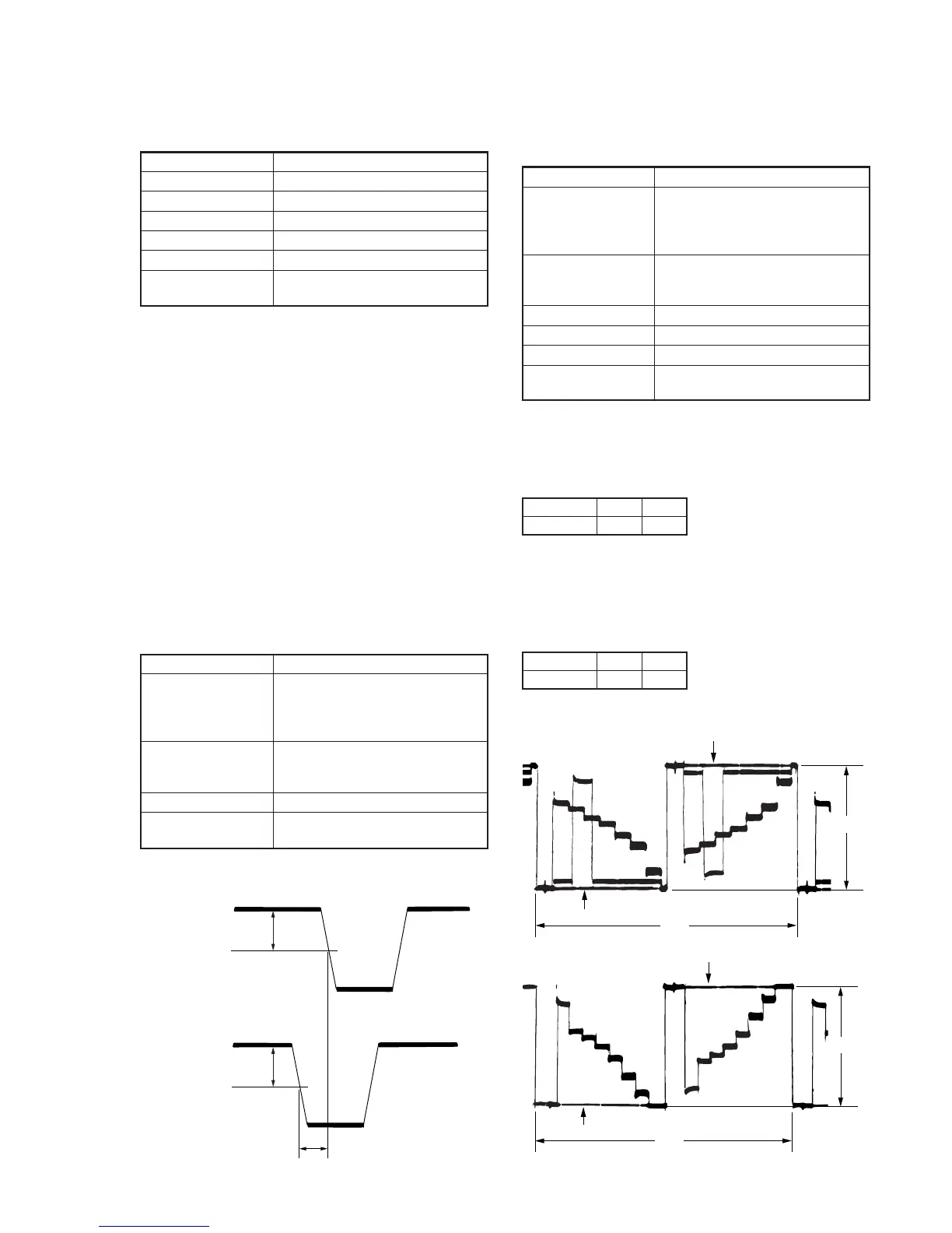
Checking method:
1) Check that the delay time (T) satisfies the specified value.
Fig. 5-1-16
T
1.5V
1.5V
PANEL XHD
HSY
4. D range Adjustment (PD-98 board)
Set the D range of the RGB decoder used to drive the LCD to the
specified value. If deviated, the LCD screen will become blackish
or saturated (whitish).
Mode VTR playback
Signal Alignment tape:
For audio operation check
(XH5-3 (NTSC))
(XH5-3P (PAL))
Measurement Point Pin 2 of CN5501 (VG)
External trigger : Pin 4 of CN5501
(PANEL COM)
Measuring Instrument Oscilloscope
Adjustment Page D
Adjustment Address 63
Specified Value A = 3.00 ± 0.05V (NTSC)
A = 3.00 ± 0.05V (PAL)
Adjusting method:
1) Select page: 0, address: 01, and set data: 01.
2 Input the following data to page: D, address: 82 and 83
Note: Press the PAUSE button of the adjustment remote commander
each time to set the data.
3) Select page: D, address: 63, change the data and set the voltage
(A) between the reversed waveform pedestal and non-reversed
waveform pedestal to the specified value.
4) Press the PAUSE button of the adjusting remote commander.
5) Input the following data to page: D, address: 82 and 83.
Note: Press the PAUSE button of the adjustment remote commander
each time to set the data.
6) Select page: 0, address: 01, and set data: 00.
For NTSC model
For PAL model
Fig. 5-1-17
Address
Data
82
00
83
00
Address
Data
82
20
83
20
 Loading...


