2-6
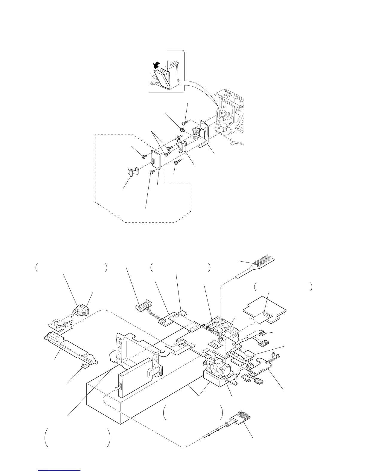
2-12.FP-647, FP-648 FLEXIBLE BOARD, VI-148 BOARD
2-13.SERVICE POSITION (For adjustment, check or voltage measurement, mainly)
Firstly, remove the following parts refering sections 2-1 and 2-2, and connect parts as shown below.
2
Screw (M2
×
3)
2
Screw (M2
×
3)
5
Screw (B2
×
5)
5
Screw (B2
×
5)
5
Screw (B2
×
5)
6
Screw (M2
×
3)
4
Jack cover
(AV)
8
FP-647 flexible boar
7
Jack frame
3
VI-148 board
1
FP-648
flexible board
Except AEP, UK model
Cassette lid open/close switch
Keep it ON by holding this switch
with adhesive tape.
PS-4580 block
FK-4580 block
Eject switch
Cabinet (L) assembly
LCD block (PD-98 board),
EVF block (VF-121 board),
KY-39 board, function switch,
flexible board
Base
Support the lens block,
VC-206 board and cabinet
(L) assembly using bases.
Lens block
Multi CPC jig
(J-6082-311-A)
MA-322 board
VI-148 board
FP-647
flexible board
Extension cord
(J-6082-413-A)
AU-202 board (CN7501)–
VC-206 board (CN9902)
CPC-8 jig
(J-6082-388-A)
Mechanism deck
CPC
Extension cord
(J-6082-414-A)
DD-106 board (CN3902) –
VC-206 board (CN9911)
DD-106 board
Battery terminal
VC-206
Board
AU-202
Board
 Loading...


