5-20
4. Contrast Adjustment (VF-121 board)
Set the level of the VIDEO signal for driving the LCD to the specified
value. If deviated, the screen image will be blackish or saturated
(whitish).
Mode VTR stop
Signal No signal
Measurement Point Pin @º of CN9903 (EVF VG) on
VC-206 board
Measuring Instrument Oscilloscope
Adjustment Page D
Adjustment Address 73
Specified Value A = 1.45 ± 0.1V (NTSC)
A = 1.35 ± 0.1V (PAL)
Adjusting method:
1) Select page: 0, address: 01, and set data: 01.
2) Select page: 2, address: 11, set data: 04, and press the PAUSE
button of the adjustment remote commander.
3) Input the following data to page: D, address: 88 to 8D.
Note: Press the PAUSE button of the adjustment remote commander
each time to set the data.
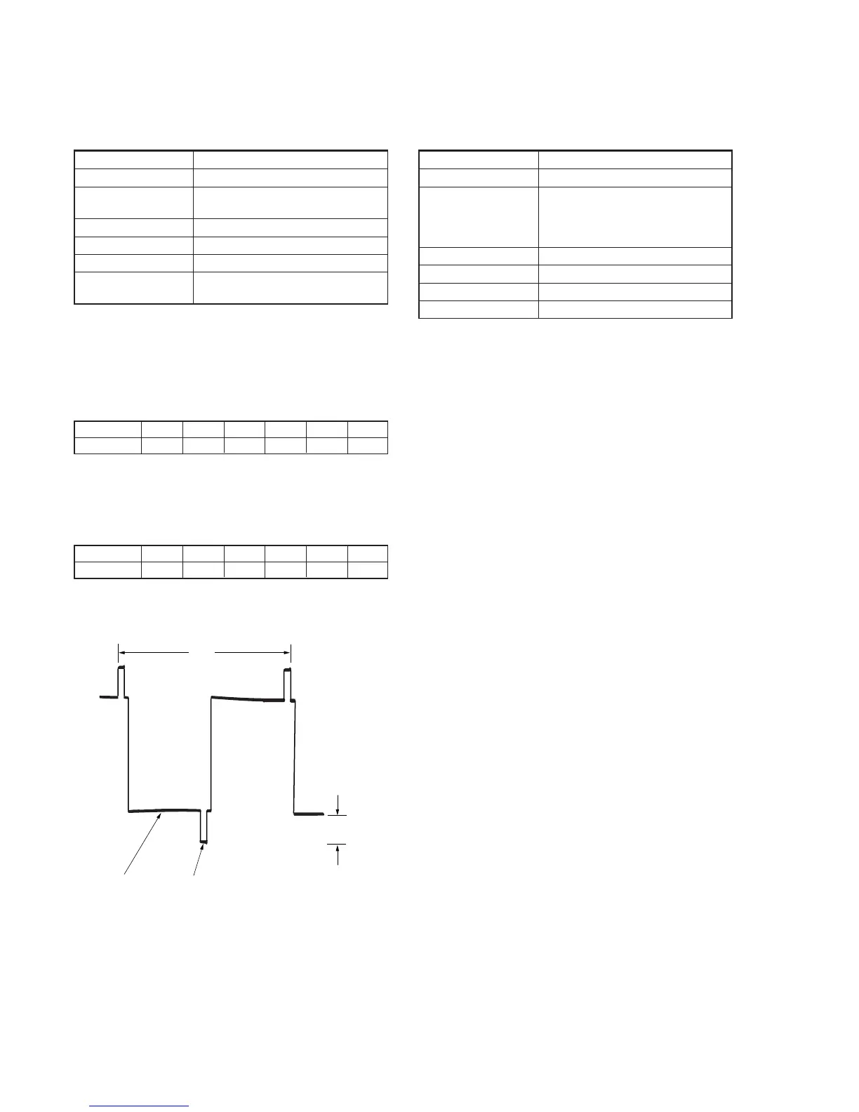
4) Select page: D, address: 73, change the data and set the voltage
(A) between the white (30%) and pedestal to the specified value.
5) Press the PAUSE button of the adjustment remote commander.
6) Input the following data to page: D, address: 88 to 8D.
Note: Press the PAUSE button of the adjustment remote commander
each time to set the data.
7) Select page: 2, address: 11, set data: 00, and press the PAUSE
button of the adjustment remote commander.
8) Select page: 0, address: 01, and set data: 00.
Fig. 5-1-14
Address
Data
88
00
89
27
8A
00
8B
00
8C
00
8D
00
Address
Data
88
38
89
00
8A
20
8B
20
8C
00
8D
00
2H
White (30%)
Pedestal
A
5. Backlight Consumption Current Adjustment
(VF-121 board)
Set the backlight luminance and color temperature.
If deviated, the image may become dark or bright.
Mode VTR stop
Signal No signal
Measurement Point + Probe: Pin !¢ of CN9903
(EVF BL 4.75V) on VC-206 board
– Probe: Pin !§ of CN9903
(EVF BL 4.75V(–)) on VC-206 board
Measuring Instrument Digital voltmeter
Adjustment Page D
Adjustment Address 77
Specified Value A = 21.0 ± 1.0mVdc
Note: Adjust 30 seconds after running on the power supply. Adjusting
method:
1) Select page: 0, address: 01, and set data: 01.
2) Select page: D, address: 77, change the data and set the voltage
difference (A) between Pin !¢ of CN9903 (EVF BL 4.75V)
and Pin !§ of CN9903 (EVF BL 4.75V(–)) to the specified
value.
3) Press the PAUSE button of the adjustment remote commander.
4) Select page: 0, address: 01, and set data: 00.
 Loading...


