131MS 261, MS 261 C
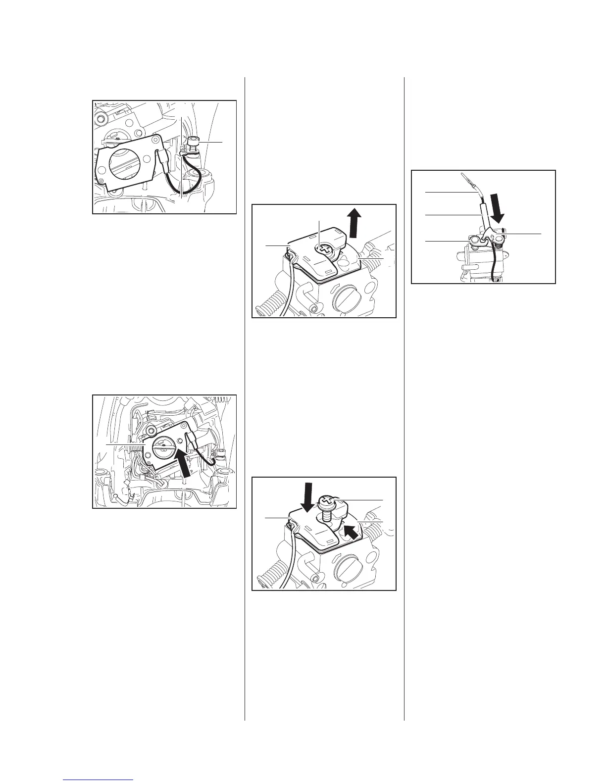
Installing
: Position the wire (1) of the
carburetor's heating element so
that the crimped side of the
terminal faces down.
: Position the ground wire (2) so
that the crimped side of the
terminal faces up.
: Insert and tighten down the
screw (3) firmly.
Do not twist the terminals.
: Fit the heating element (1).
– Reassemble all other parts in the
reverse sequence.
5902RA517 TG
3
1
2
5902RA609 TG
1
13.1.3 Thermostatic Switch
The thermostatic switch is an
electronic component that cannot
be tested directly. Its operation can
be checked with the aid of the
troubleshooting chart, b
12.5
: Take out the screw (1) with
washers.
: Remove the thermostatic
switch (2).
– Hold the end cover (3) so that the
pump diaphragm and gasket
remain in position.
Installing
– Check that the pump diaphragm
and gasket are properly seated.
– Hold the end cover (3) so that the
pump diaphragm and gasket
remain in position.
5902RA392 TG
1
3
2
5902RA399 TG
3
2
1
: Position the thermostatic
switch (2) so that it butts against
the hump (arrow).
: Fit the screw (1) with washers
and tighten it down firmly.
: Fit the wire (1) behind the
levers (2) and (3).
: Fit the insulating tube (4).
– Install the carburetor, b
 Loading...