80 MS 261, MS 261 C
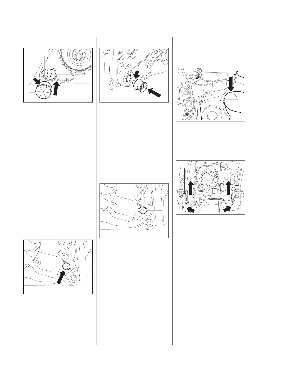
Installing
– Position the stop buffer (1)
with its tapered end facing the
crankcase.
– Use STIHL press fluid to simplify
assembly,
15
: Push home the stop buffer (1)
until its groove (arrow) engages
the housing rib (2).
– The peg (3) must engage the
stop buffer (1).
9.5.1 Stop Buffer at Ignition
Side
– Remove the ignition module,
7.3
– Remove the tank housing,
12.11.5
: Ease the stop buffer (1) out of the
bore.
– Check the stop buffer (1) and
replace if necessary
5902RA249 TG
1
3
2
5902RA250 TG
1
Installing
– Position the stop buffer (1)
with its tapered end (arrow)
facing the crankcase.
– Use STIHL press fluid to simplify
assembly, b
15
: Push the stop buffer (1), tapered
end inside the crankcase, fully
into the bore.
– Turn the stop buffer back and
forth to simplify installation.
The tapered end (1) must be
properly seated in the bore at the
ignition side.
– Reassemble all other parts in the
reverse sequence.
5902RA251 TG
1
5902RA252 TG
1
9.5.2 Buffers on Filter Base
– Remove the filter base, b
7.3
: Take out the screw (1).
: Press the tank housing (2) down
a little and hold it there.
: Push out the buffers (1) from the
underside (arrows).
– Check the buffers (1) and replace
if necessary
1
5902RA253 TG
2
5902RA254 TG
1 1
 Loading...