133MS 261, MS 261 C
13.3 Handle Heating System
13.3.1 Troubleshooting
The entire handle heating system is
maintenance-free and subject to
practically no wear. Faults in the
generator, heating elements and
wiring are generally caused by
mechanical damage.
There are two reasons for failures in
the heating system:
1. A break in the
circuit due to a
faulty wire or
component.
2. A short circuit
resulting from damage to the
insulation.
– Remove the handle molding,
10.2
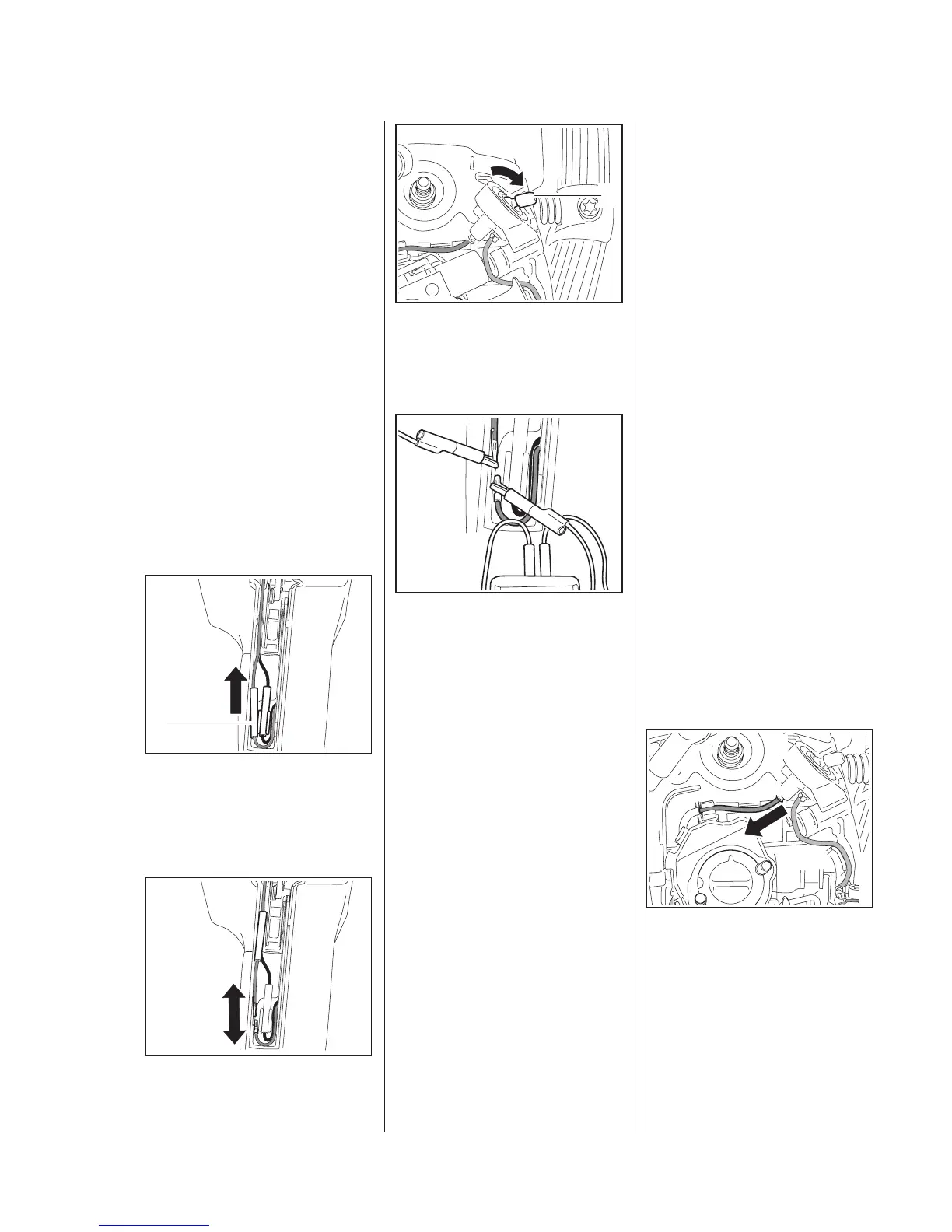
: Pull one of the connectors out of
the guide and push the insulating
tube (1) in the direction of the
wiring harness.
: Separate the pin and socket
connector.
5902RA518 TG
1
5902RA519 TG
: Set the heater switch (1) to "F".
– Set the ohmmeter to "Ω".
– Set the Master Control lever to
"
0".
: Clip the test leads to the wire
from the wiring harness and the
rear handle heating element wire.
Carburetor Heating
– Separate the pin and socket
connector to the thermostatic
switch, b
13.1.3
All electrical components of the
handle heating system are
connected in series with the
ohmmeter.
If the system is in order, the
ohmmeter will indicate a value of
about 10 Ω in measuring range "Ω".
If no reading is obtained, there is a
break in the circuit.
5902RA573 TG
1
5902RA574 TG
If the ohmmeter shows a very low
value, there is a short circuit in one
of the components.
In either case it is necessary to
check each component separately.
The generator wire remains
disconnected from the thermostatic
switch during this check.
– Use handle heating and
generator troubleshooting chart
to check the system, b
13.7.1
– Check resistance on handlebar,
13.6
– Check resistance on rear handle,
13.5
– After completing the test,
reconnect the wires and push the
insulating tube over the pin and
socket connector.
– Reassemble in the reverse
sequence.
13.4 Heater Switch
– Remove the carburetor,
12.5
: Pull off the connector sleeve (1).
5902RA575 TG
1
 Loading...