79MS 261, MS 261 C
9.4.1 Models with Heating
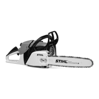
– Push the air guide shroud (1) in
direction of rear handle.
: Take out the screws (2) and (3).
: Remove the complete AV
spring (4).
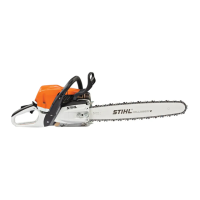
: Unscrew the bearing plug (1) and
disconnect the retainer (arrow).
: Unscrew the spring (2) and pull
out the retainer (arrow).
5902RA245 TG
1
3
4
2
0001RA219 TG
1
2
Installing
: Fit the retainer (1) in the
bracket (2) and engage the
nipple.
: Screw the spring (2) onto the
peg.
: Attach the retainer (arrow) to the
bearing plug (1).
: Screw the bearing plug (1) into
the spring (2) as far as stop.
: Position the AV spring (4) on the
handlebar and cylinder.
: Insert and tighten down the
screw (2) firmly.
5902RA246 TG
2
1
0001RA219 TG
1
2
5902RA247 TG
1
3
4
2
: Push the air guide shroud (1) in
direction of rear handle.
: Coat the screw (3) with Loctite, fit
it and tighten it down firmly, b
15
– Reassemble all other parts in the
reverse sequence.
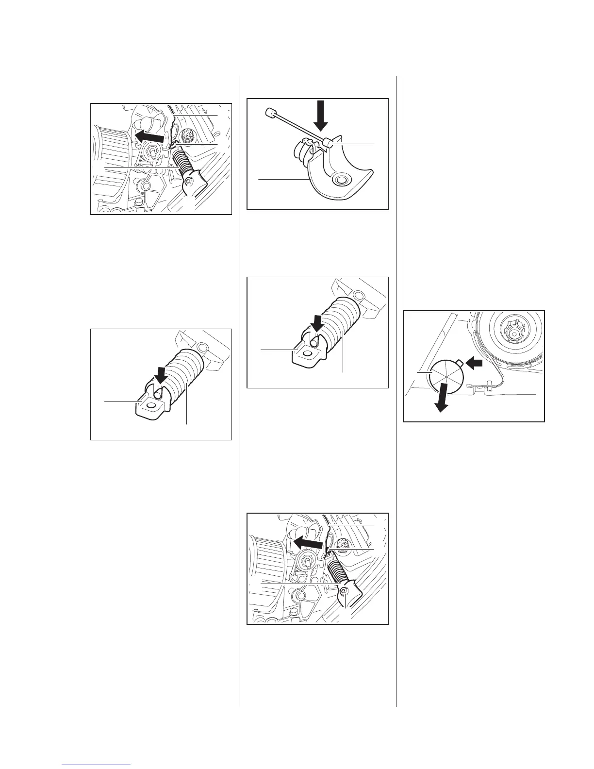
9.5 Stop Buffer at Clutch
Side
The stop buffers are located
between the tank housing and
crankcase. They are fitted at the
ignition and clutch sides.
Stop buffer at clutch side
: Pry out the stop buffer (1) at the
recess (arrow).
– Check the stop buffer and
replace if necessary.
5902RA248 TG
1
 Loading...