54 MS 261, MS 261 C
The setting gauge is not shown in
the illustration.
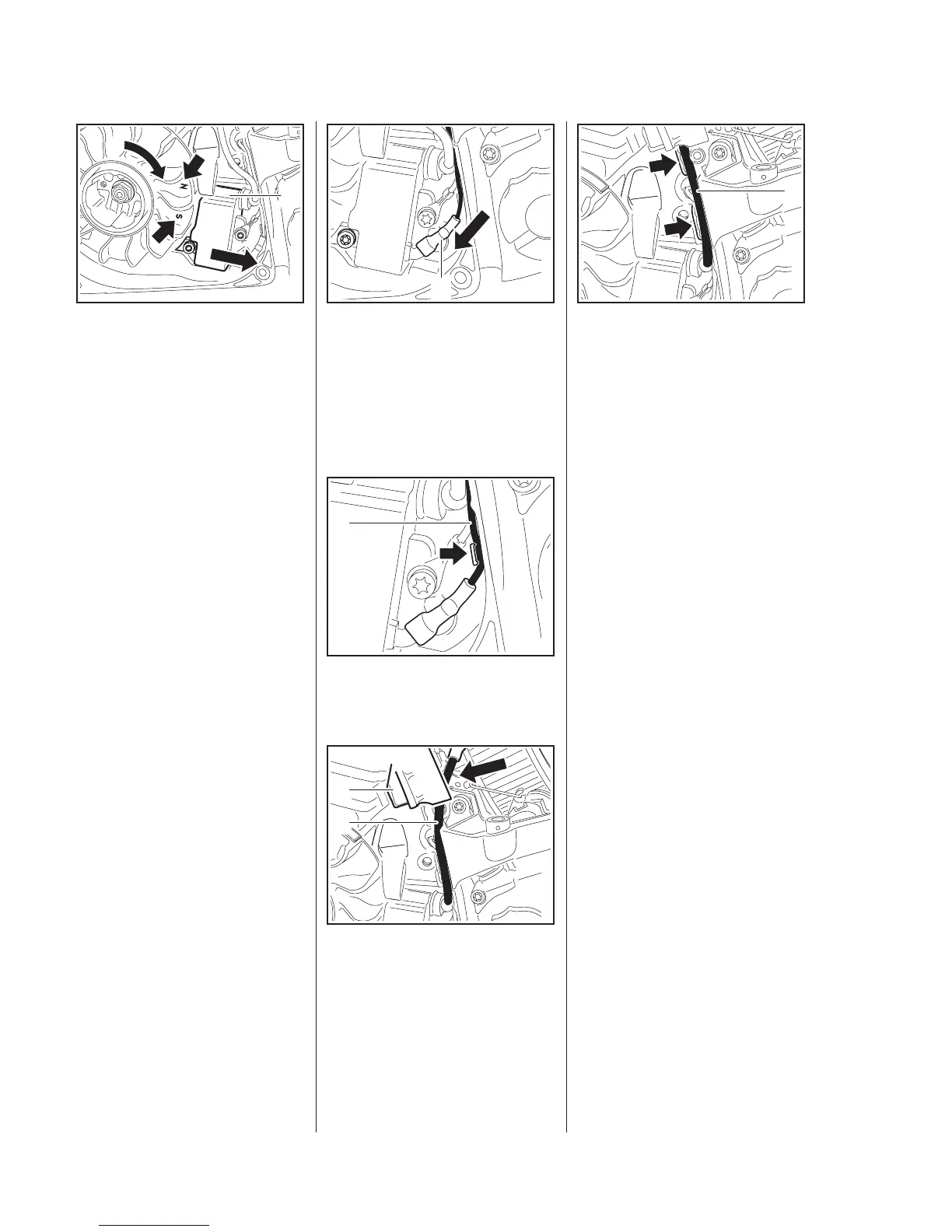
– Push the ignition module (1) back
and hold it there.
– The flywheel must rotate freely.
: Rotate the flywheel until the
magnet poles (arrows) are next
to the ignition module (1).
– Press the ignition module (1)
against the setting gauge.
– Position the ground wire terminal
so that it points in the direction of
the cable guide.
– Tighten down the screws firmly.
– Remove the setting gauge.
– Check operation.
– Rotate the flywheel and make
sure it does not touch the ignition
module.
5902RA173 TG
1
Crimped side of terminal (1) must
face the crankcase.
: Connect the short circuit wire
terminal (1)
– the terminal must be pushed
fully home.
: Press the short circuit wire (1)
fully into the guide (arrow).
: Lift the air guide shroud (1) a little
and push the ignition lead (2) into
position
– take care not to distort the air
guide shroud.
5902RA174 TG
1
5902RA602 TG
1
5902RA175 TG
1
2
: Starting at the ignition module,
press the ignition lead (1) into the
guides (arrows).
– Reassemble all other parts in the
reverse sequence.
7.4 Testing the Ignition
Module
To test the ignition module, use
either the ZAT 4 ignition system
tester 5910 850 4503 or the ZAT 3
ignition system tester
5910 850 4520.
The ignition test refers only to a
spark test, not to ignition timing.
1
5902RA176 TG
 Loading...