30 MS 261, MS 261 C
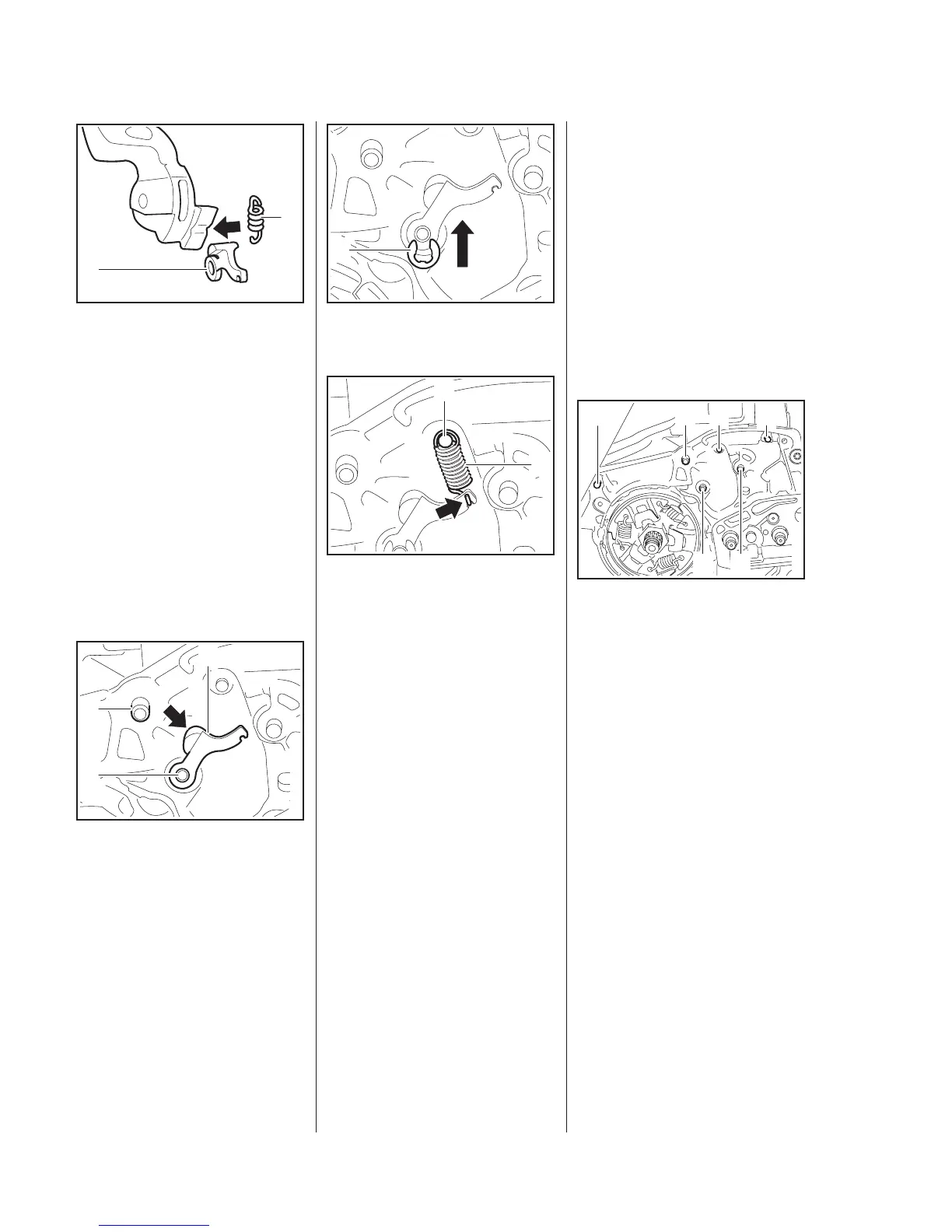
: Check the cam lever (1) and
spring (2) and replace if
necessary.
: Check the condition of the cam
contour (arrow) and replace the
hand guard if necessary.
– Inspect all pivot pins and replace
if necessary,
5.6
Installing
– Lubricate the pivot pins,
15
– Position the cam lever (1) so that
its cam (arrow) faces the pin (3).
: Push the cam lever (1) on to the
pivot pin (2).
5902RA070 TG
2
1
5902RA071 TG
1
2
3
: Fit the E-clip (1).
: Attach the spring (1) to the cam
lever so that the open side of the
spring hook (arrow) is visible.
: Attach the spring (1) to the
anchor pin (2).
The cam lever is not yet under
tension – the spring may become
detached.
– Reassemble all other parts in the
reverse sequence.
– Lubricate the cam lever, b
15
5902RA072 TG
1
5902RA073 TG
1
2
5.6 Pins
The anchor and pivot pins secure
the springs. Worn pins must be
replaced.
– The springs may otherwise
become detached and pop out.
The pins must be driven home
squarely.
For greater clarity, all parts have
been removed from the pins in the
following illustrations.
: Remove the pins (1) to (6).
Pin 6 is fitted only on machines with
QuickStop Super.
5902RA074 TG
2
13
4
5
6
 Loading...