COMPONENT INFORMATION
2-15
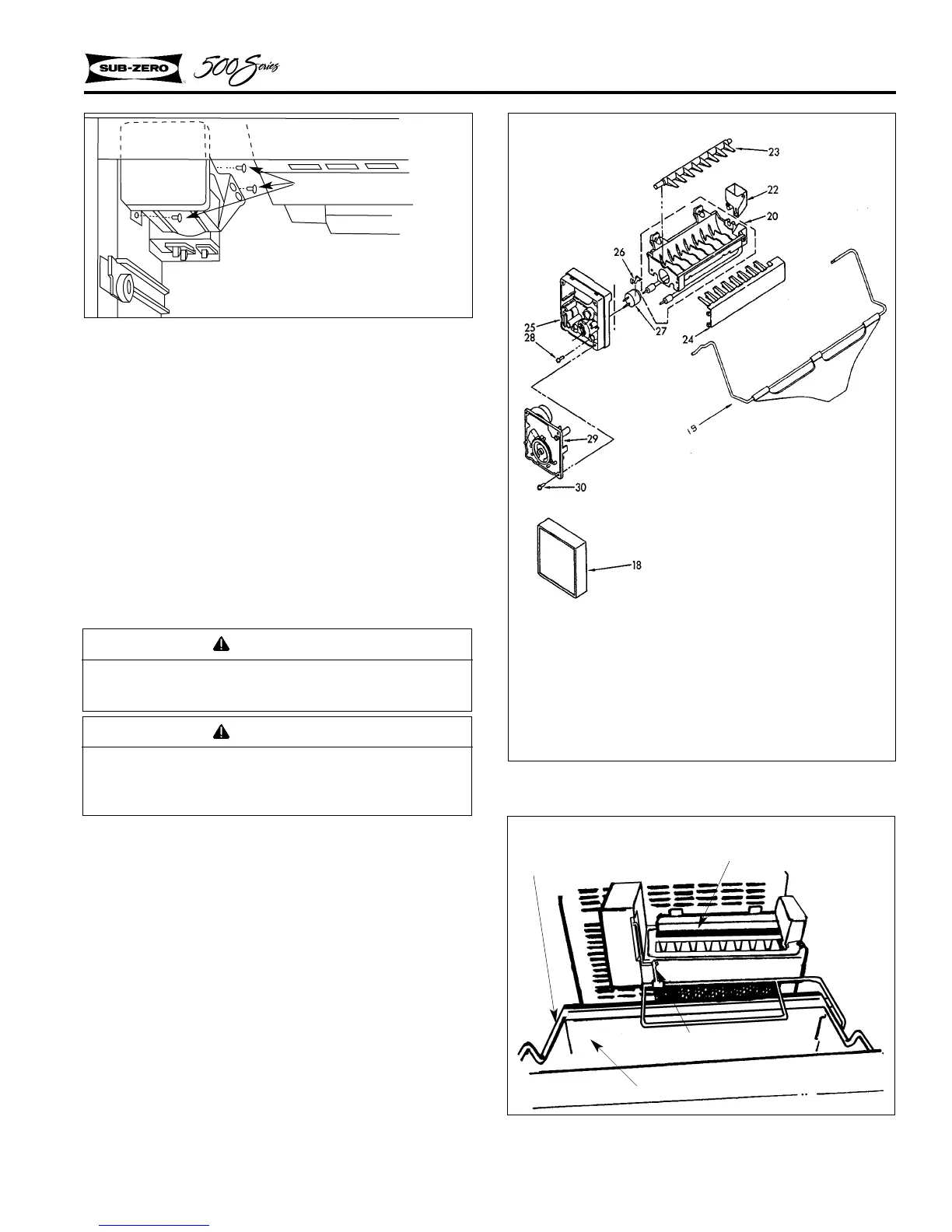
Figure 2-40. Modular Icemaker
Models 511, 550
18. Cover
19. Ice Maker Arm
20. Mold & Heater Assy.
(Silicone Grease)
22. Bearing & Inlet
23. Ejector
24. Ice Stripper
25. Support
26. Retainer, Thermostat
27. Thermostat
28. Screw, #10-32 x 43/64
29. Module & Motor Assy.
30. Screw, #8-18 x 11/16
Figure 2-41. Ice Bucket
Models 532, 542, 561
Connecting Rod
Carriage Assy.
Modular Ice Maker
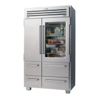
Figure 2-39. Models 511, 550 Icemaker
Mounting Screws
1. To remove the icemaker, extract the mounting
screw at the bottom of the icemaker which
secures the icemaker bracket to the left side
wall.
2. Then extract the two mounting screws at the
top, above the icemaker mold (Figure 2-39).
3. Pull the icemaker assy. down and disconnect
the electrical leads from the icemaker.
Ice Maker Assembly - Models 532, 542, 561
The back channel of the ice bucket hooks over the
ice bucket carriage assembly (Figure 2-41).
The guide on the carriage assy. contacts the arm of
the ice maker linkage (Figure 2-42). As the car-
riage assy. is pulled out, the arm rides up the guide
and the linkage will raise allowing clearance for
the ice bucket. When the carriage is pushed back,
the linkage drops into the ice bucket to sense the
level of the ice.
WARNING
Always disconnect electrical power to equip-
ment before attempting repairs.
CAUTION
Do not manually advance the ejector blades on
a modular ice maker or the unit will be dam-
aged.
Ice Bucket
 Loading...