COMPONENT INFORMATION
2-23
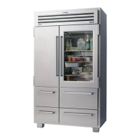
Figure 2-63. Control Panel
Model 590
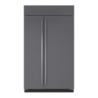
5. The freezer control bulb is inserted through a
vinyl sleeve that leads to the freezer section.
6. When reinstalling, route the control bulb
through a grommet to the freezer section, then
downward into a plastic sleeve. The end of
the control bulb should extend approximately
1” from the plastic sleeve (Figure 2-64).
Bulk Ice Switch - Model 590
1. Remove the water tank cover to access the
bulk ice switch (Figure 2-63).
2. Remove the mounting screw located on the
backside of the control panel, then remove the
control assy.
3. Remove the three panel screws (Figure 2-63).
4. Remove the switch by pressing in the tabs
securing the switch to the panel.
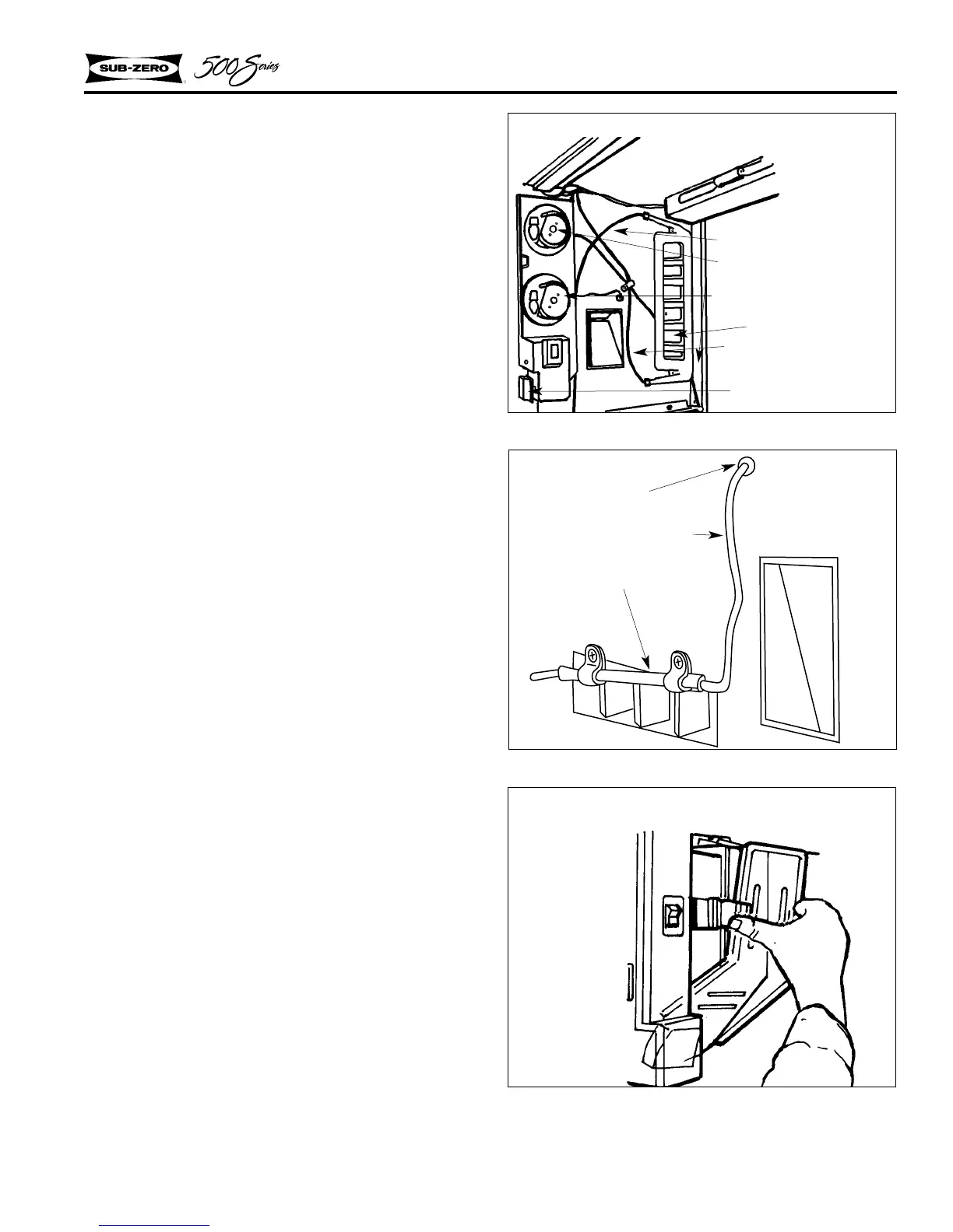
Ice Chute - Model 590
The ice chute is mounted to the center mullion
wall (Figure 2-65). If there is a blockage in the
chute, remove the water tank cover (Figure 2-61),
then depress the two tabs so the front portion of
the chute can be removed.
Water Tank Reservoir - Model 590
The water tank reservoir is held in place with three
screws (Figure 2-63). The inlet tube at the bottom
draws water in from the water valve, the outlet
tube at the top carries the water to the dispensing
unit.
Refrigerator Control
Freezer Control
Water Tank
Outlet Tube
Inlet Tube
Bulk Ice Switch
Figure 2-64. Freezer Bulb Routing
Model 590
Figure 2-65. Ice Chute
Model 590
Grommet
Freezer Control Bulb
Plastic Sleeve
 Loading...