COMPONENT INFORMATION
2-25
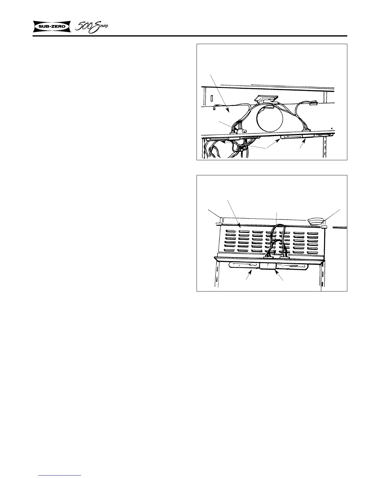
Figure 2-68. Thermal Switch-Refrigerator
All Models
LIGHT TERMINATOR
To prevent damage to plastic parts by lights over-
heating, a thermal switch is incorporated into the
light system wiring. This design was incorporated
starting with the following serial numbers:
Model Serial Number
501R M723972 / P725922
501F M724222 / P726372
511 M753523
550 M722972 / P721572
532 M722572 / P725022
542 Regardless of Serial Number
561 M726672 & P725322
590 Regardless
The thermal switch specifications are:
Opens: 120
°F+/-6°F
Closes: 85
°F+/-7°F
On units equipped with the thermal switch, the
lights will go off if the door is left open for
extended periods (20-25 minutes). To reset the
thermal switch, close the door for approximately
20 minutes. The light should then come back on
when the door is opened. If it does not, the ther-
mal switch may be faulty.
Before replacing the switch, check the mounting
of the switch on the fan guard. It may be neces-
sary to add a 1/8” stainless steel washer between
the switch and the guard to prevent the bi-metal in
the fuse from compressing (and opening) when the
door is opened again.
NOTE: The thermal switch cannot be retrofitted to
units built prior to the serial numbers listed above.
The entire fan shroud assembly must be replaced.
See Figures 2-68 & 2-69 for thermal switch loca-
tion.
Figure 2-69. Thermal Switch-Freezer
Model 532, 542, 561
Light Bulb
Light Socket
Fan Shroud
Thermal Switch
Light Bulb
Light Socket
Fan Shroud
Thermal Switch
 Loading...