4-4 ELECTRICAL
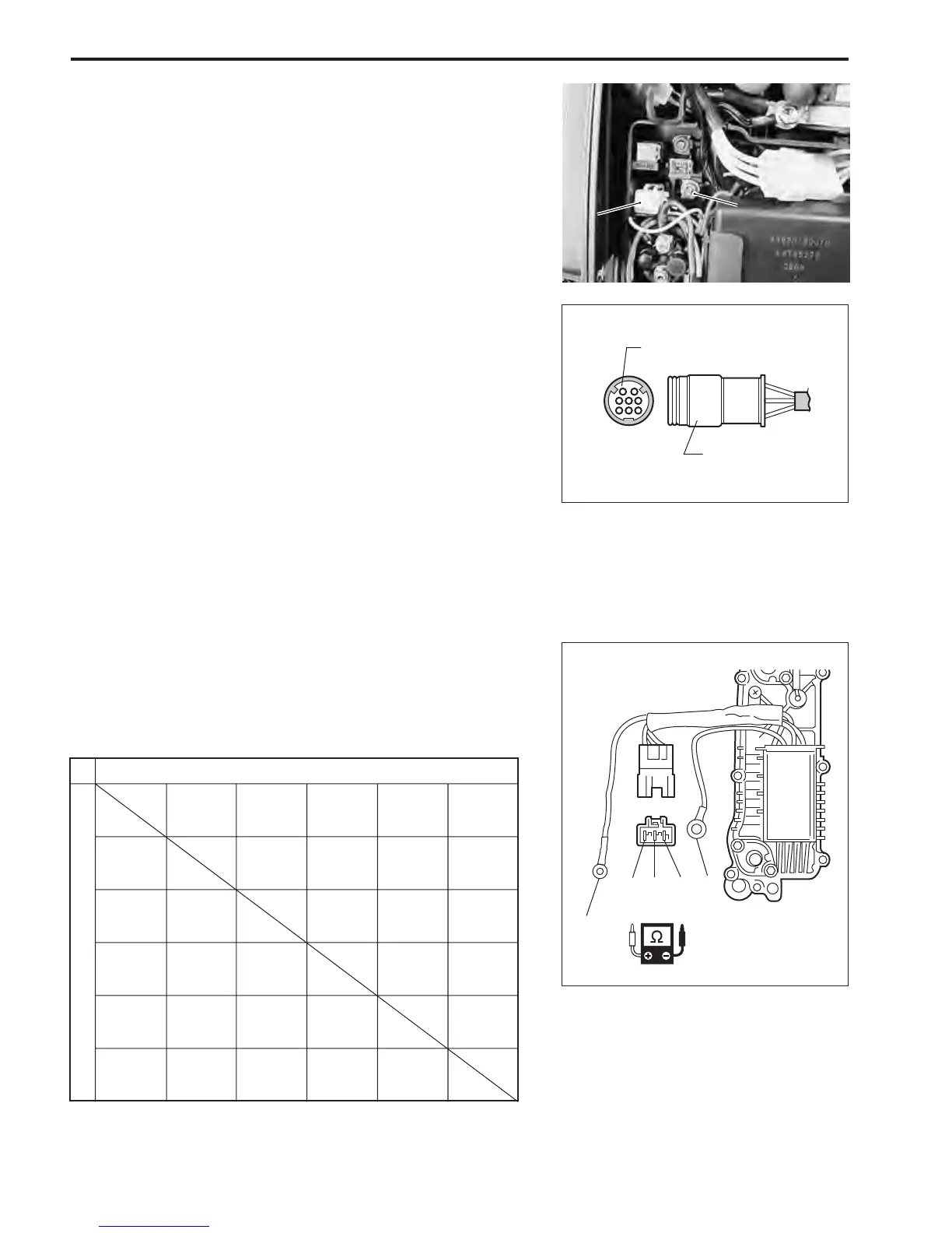
RECTIFIER & REGULATOR
\ 09900-25010 : Pocket tester
V Tester range : ×1 k
ΩΩ
ΩΩ
Ω (Resistance)
1. Disconnect all lead wires of rectifier & regulator.
2. Measure resistance between leads in combinations shown.
NOTE:
The values given below are for a SUZUKI pocket tester.
As thyristors, diodes, etc. are used inside this rectifier & regu-
lator, the resistance values will differ when an ohmmeter other
than SUZUKI pocket tester is used.
Rectifier & regulator resistance :
If measurement exceeds specification, replace rectifier & regu-
lator.
Tester probe + (Red)
Tester probe - (Black)
Black White
White 1
White 2
White 3
Black
White
White 1
White 2
White 3
Unit : Approx. k
ΩΩ
ΩΩ
Ω
Sub fuse case
1. Disconnect white lead wire of fuse case from terminal (B).
2. Inspect continuity between White lead wire with plate ter-
minal and White lead wire of main harness 8P connector.
If no continuity is exists, replace main harness and/or fuse.
B
2
B
2
2. Sub fuse2. Sub fuse
White lead wire
8P Connector
0.5~10
W1
W2
W3
B
W
0.5~10
0.5~10
4~80
4~80
4~80
3~60
1~20
5~1005~100
5~100
5~1005~100
5~100
4~804~804~80
0.5~1000.5~1000.5~100
 Loading...


