DF140 “K2” (’02) MODEL 11-39
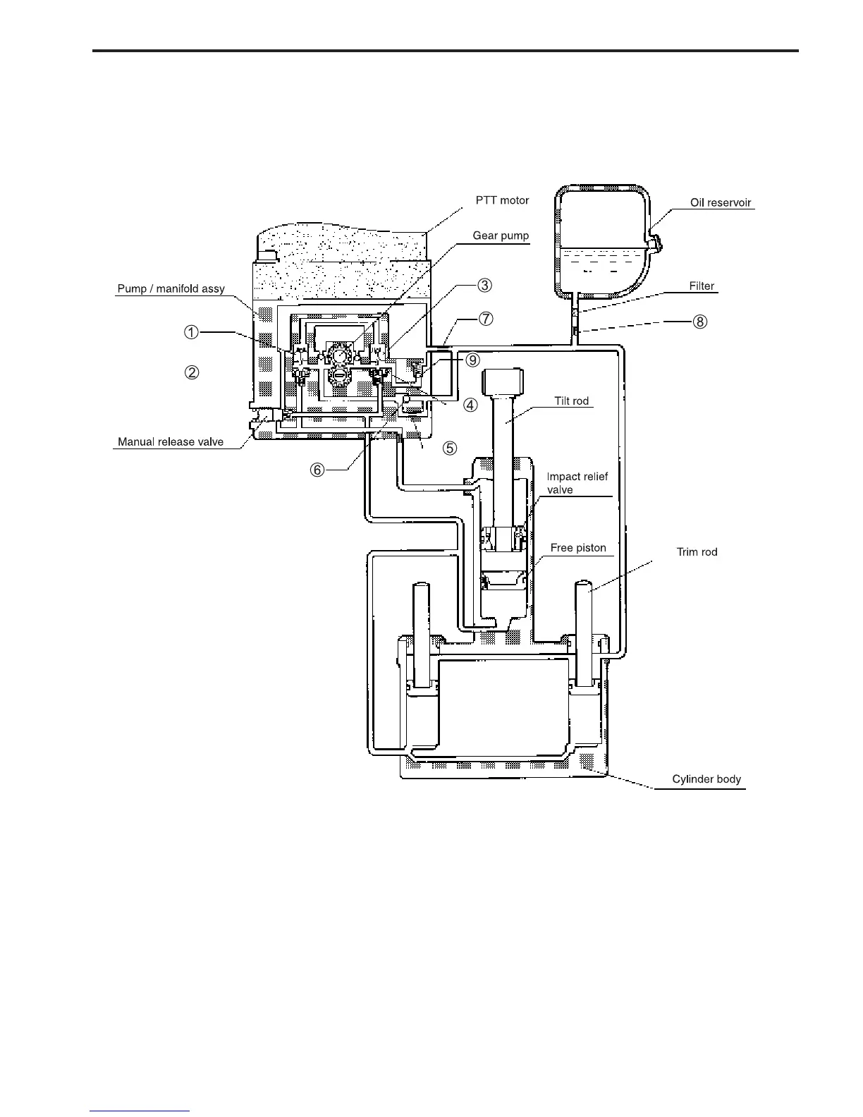
COMPONENT PARTS
1 Down shuttle valve
2 Down check valve
3 Up shuttle valve
4 Up check valve
5 Down relief orifice
6 Down relief check valve
7 Pump room orifice
8 Tank room orifice
9 Up relief valve
* When the manual valve is to be opened, turn the manual release valve to the left about two turns.
* When the oil level of the system should be checked, inspect the reservoir by placing the motor in the maximum tilt up position.
OPERATION
By motor operation, the geared pump will be driven, and by turning the motor to the right or to the left, oil flow
will change its direction, and this causes up and down movements of the piston rod of the tilt cylinder and the
trim rod of the trim cylinder.
 Loading...


