4-6 ELECTRICAL
INSTALLATION
Installation is reverse order of removal with special attention
to the following step.
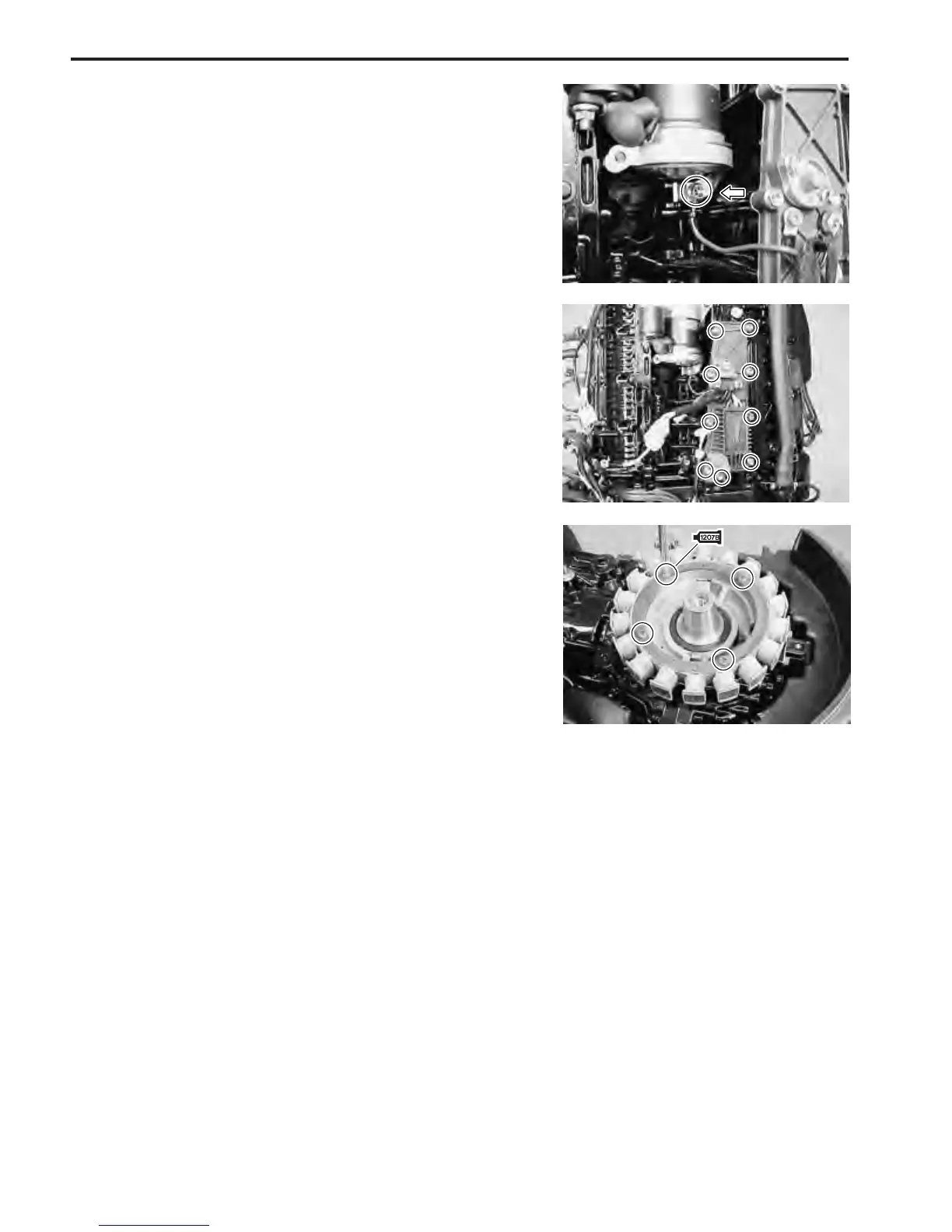
Battery charge coil
Apply Suzuki Bond to coil securing screws.
D 99000-31140 : Suzuki Bond 1207B
Wire routing
Check wire routing. (See page 10-2 to 10-7)
Rectifier & regulator
1. Remove electric parts holder. (See page 4-25)
2. Remove bolt securing ground lead wire of Rectifier & regu-
lator.
3. Remove bolts securing exhaust cover (Rectifier & regu
lator).
4. Remove exhaust cover with rectifier & regulator.
 Loading...


