Home
Suzuki
Outboard Motor
DF140WT
Suzuki DF140WT User Manual
4
of 1
of 1 rating
616 pages
Give review
Manual
Specs
To Next Page
To Next Page
To Previous Page
To Previous Page
Loading...
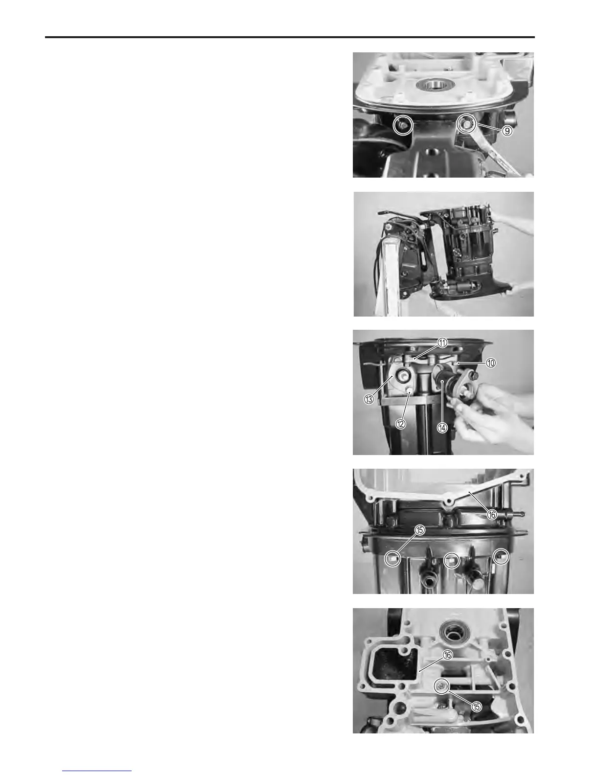
7-4 MID UNIT
14.
Remove f
our bolts
E
and engine holder
F
.
11.
Remove tw
o bolts
0
and clutch shaft holder
A
.
12.
Remove f
our bolts
B
and upper mount cov
er
C
.
13.
Remove upper mount assemb
lys
D
.
9.
Remo
ve tw
o upper mount nuts
9
and washers.
10.
Remove driv
eshaft housing with oil pan.
213
215
Table of Contents
General Information 1
5
Engine Control System
2
Fuel System
2
Product View and Components
3
How to Use this Manual
3
Symbol Description
4
Table of Contents
5
General Information
2
Warning / Caution / Note
6
General Precautions
6
Identification Number Location
8
Fuel and Oil
8
Gasoline Recommendation
8
Engine Oil
8
Engine Break-In
9
Propellers
10
Powerhead Direction of Rotation
10
Specifications
11
General Specification
12
Service Data
13
Self-Diagnostic System Indication
19
Tightening Torque
20
Special Tools
22
Materials Required
25
Periodic Maintenance 2
26
Periodic Maintenance Schedule
27
Periodic Maintenance Chart
27
Maintenance and Tune-Up Procedures
28
Engine Oil / Engine Oil Filter
28
Engine Oil Change/Engine Oil Filterreplacement
29
Gear Oil
31
Lubrication
32
Spark Plug
33
Tappet Clearance
34
Idle Speed
39
Ignition Timing
40
Breather and Fuel Line
41
Low Pressure Fuel Filter
41
High Pressure Fuel Filter
42
Water Pump / Water Pump Impeller
42
Propeller / Nut / Cotter Pin
42
Anodes and Bonding Wires
43
Battery
44
Bolt and Nuts
45
Feedback)
45
Oil Pressure
46
Cylinder Compression
48
Engine Control System
49
Engine Control System Structure
50
System Structure 1
50
System Structure 2
51
Wiring Diagram for Engine Control
52
Components for System Control
53
Engine Control Module (Ecm)
53
Ecm Connector / Terminals Layout
54
Ecm Internal Structure
55
Sensor and Switch
56
Ignition System
60
Ignition Control System
60
Electronic Fuel Injection System
62
Fuel Injection Control System
62
Fuel Delivery System Components
64
Fuel Pump Control System
67
Air Intake Components
68
Idle Air Control System
69
Caution System
71
Over-Revolution Caution System
71
Low Oil Pressure Caution System
72
Overheat Caution System
73
Low Battery Voltage Caution System
74
Self-Diagnostic System
75
Priority / Code / Pattern for Self-Diagnostic System Operation
75
Condition for Self-Diagnostic System Operation
77
Fail-Safe System
78
Pre-Programmed Value for Fail-Safe System
78
Operating Hour Indication System
79
Oil Change Reminder System
80
Start-In-Gear Protection System
81
O 2 Feedback System
82
Inspection
83
Precaution on System Inspection
83
44-Pin Test Cord
83
Inspection for Ecm Circuit Voltage
84
Inspection for Resistance
86
Component Inspections
87
Troubleshooting
93
Removal / Installation
99
Flywheel
99
Ckp Sensor / Cmp Sensor
99
Oil Pressure Switch
102
Electrical
103
Battery Charging System
104
Outline
104
Inspection
105
Removal / Installation
107
Electric Starter System
109
Outline
109
Troubleshooting
111
Inspection
112
Starter Motor
114
Disassembly
115
Inspection & Servicing
118
Assembly
123
Performance Test
124
Monitor-Tachometer
126
Inspection
126
Erectric Parts Holder
127
Fuel System
128
Default Chapter
128
Removal / Installation
128
Precaution on Fuel System Service
129
General Precaution
129
Fuel Pressure Relief Procedure
130
Removal / Installation
131
Fuel Line ______________________________________________ 5-4
131
Fuel Leakage Check Procedure
131
Fuel Hose Connection
132
Fuel Pressure Inspection
132
Fuel Vapor Separator / High Pressure Fuel Pump
134
Removal / Installation
134
Disassembly
135
Inspection
136
Assembly
137
Fuel Injector
139
Inspection
139
Removal
139
Installation
140
Low Pressure Fuel Pump
141
Removal / Installation
141
Disassembly / Reassembly
142
Inspection
143
Fuel Tank
144
Disassembly / Reassembly
144
Inspection
145
Power Unit
146
Intake Manifold Assembly
147
Removal
147
Installation
149
Power Unit
150
Removal
150
Installation
154
Oil Pump
157
Removal
157
Inspection
157
Installation
158
Timing Chain / Tensioner
159
Removal
159
Inspection
161
Installation
162
Cylinder Head Assembly
165
Removal
165
Installation
166
Disassembly
169
Inspection / Servicing
170
Reassembly
183
Cylinder / Crankshaft / Piston
185
Disassembly
185
Inspection / Servicing
188
Reassembly
202
Thermostat
208
Operation
209
Water Cooling System
209
Engine Lubrication System
210
Removal / Inspection / Installation
209
MID Unit
211
Engine Side Cover
212
Removal
212
Installation
212
Driveshaft Housing and Oil Pan
213
Removal
213
Inspection
215
Assembly
217
Swivel Bracket, Steering Bracket and Clamp Bracket
223
Removal
223
Inspection
225
Reassembly
226
Clamp Bracket ________________________________________ 7-13
223
Water Pressure Valve
230
Power Trim and Tilt
231
System Wiring Diagram
232
Service Procedure
233
Oil Level
233
Air Bleeding
233
Power Trim and Tilt Unit
234
Removal
234
Disassembly
235
Inspection
237
Reassembly
239
Ptt Motor
240
Ptt Motor Removal
240
Ptt Motor Disassembly
241
Ptt Motor Inspection
242
Ptt Motor Assembly
243
Ptt Motor Installation
244
Installation
245
Ptt Motor Relay
247
Ptt Switch
248
Operation
249
Components
249
Principles of Operation
250
Lower Unit
255
Removal & Disassembly
256
Pinion Bearing
261
Inspection
263
Propeller
263
Gearcase
263
Gears
264
Propeller Shaft Components
264
Propeller Shaft Bearing Housing
264
Shift Rod Guide Housing Components
265
Water Pump and Related Items
265
Driveshaft Oil Seal Housing
266
Driveshaft
266
Assembly & Installation
267
Trim Tab
277
Lower Unit Gears-Shimming and Adjustment
278
Df140 "K2" ('02) Model
294
Specifications _________________________________________ 1
294
General Information
295
Specifications
295
Service Data
297
Tightening Torque
304
Special Tools
306
Materials Required
309
Engine Control System
310
Power Unit
311
Engine Oil Cooler
311
Camshaft
313
Cylinder Block
314
Piston & Piston Ring
314
Crankshaft
315
Conrod Assembly
315
MID Unit
316
Power Trim and Tilt
318
Service Procedure
318
Oil Level / Air Bleeding
318
Power Trim and Tilt Unit
319
Removal
319
Disassembly
320
Cleaning and Inspecting
323
Reassembly
324
Ptt Motor
326
Installation
330
Component Parts
332
Operation
332
LOWER UNIT (Normal Rotation Model)
339
Removal and Installation
339
Disassembly
339
Assembly
344
Lower Unit Gears-Shimming and Adjustment
354
Counter Rotation Lower Unit (Df140Z)
359
Removal and Installation
360
Disassembly
360
Inspection
365
Assembly
369
LOWER UNIT GEARS-SHIMMING and ADJUSTMENT (Counter Rotation Model)
379
Wiring Diagram
385
Hose Routing
386
Df90/115 "K2" ('02) Model
387
Specifications
388
Service Data
390
Tightening Torque
397
Materials Required
398
Fuel/Water Hose Routing
399
Conrod Assy and Bearing
402
Crank Pin and Conrod Bearing
402
Over-Revolution Caution System
402
Camshaft and Tappet Shim
403
Crankshaft and Flywheel
403
Engine Holder Gasket
404
Engine Holder Bolt
405
Upper Mount Front Nut
405
Clutch Linkage
406
Df90/115/140 "K3" (2003) Model
407
Service Data (Df140(W)T/140Z) __________________________ 13-13
426
Service Data (Df90T/115(W)T) ___________________________ 13-6
426
Tightening Torque
426
Ecm
427
Ecm Main Relay and Starter Motor Relay
427
Battery Charge Coil
428
Rectifier & Regulator
428
Exhaust Camshaft (for Df115 Only)
429
Remote Control Cable Holder
429
Cylinder Head Instllation
430
Crankcase to Cylinder Instllation
431
Upper Mount
432
Drive Shaft
432
Propeller Shaft Bearing Housing
432
Df115W and Df140W
433
Exhaust Valve
433
Water Pump Case
433
Ecm
433
Wiring Diagram
434
Wire Routing
435
Water Hose Routing
437
Df90/115/140 "K4" ('04) Model
438
Specifications (Df90T/115T/115Wt)
439
Specifications (Df140T/140Wt/140Z)
441
Service Data (Df90/115)
443
Service Data (Df140)
450
Cylinder Block
457
Rectifier & Regulator
457
Temperature Sensor
457
Electric Parts Holder
458
P.t.t. Motor
458
Power Trim & Tilt (P.t.t.) Relay
458
Clamp Bracket Shaft
459
Swivel Bracket
459
Tilt Limit Switch System
459
Driveshaft
460
Pinion Gear Back up Shim
460
Port Clamp Bracket
460
Lower Unit Gears-Shimming and Adjustment
461
Wiring Diagram
462
Df90/115/140 "K5" (2005) Model
463
Specifications (Df90T/115T/115Wt)
464
Specifications (Df140T/140Wt/140Z/140Wz)
466
Service Data (Df90T/115T/115Wt)
468
Service Data (Df140T/140Wt/140Z/140Wz)
475
Engine Wiring Harness
482
Safety Relay System
482
Ecm
483
Sub-Battery Cable
483
Remote Control Box and Remote Control Wire
484
Piston Oil Ring
486
Tensioner Adjuster
486
Tilt Limit Switch Cover
486
Engin Holder
487
Upper and Lower Mount
487
Transom Bolt
488
Wire/Hose Routing
489
Wiring Diagram
492
Df90/115/140 "K6" (2006) Model
493
Specifications (Df90T/115T/115Wt)
494
Specifications (Df140T/140Wt/140Z/140Wz)
496
Service Data (Df90T/115T/115Wt)
498
Service Data (Df140T/140Wt/140Z/140Wz)
505
Tightening Torque
513
Periodic Maintenance Schedule
513
Ecm
514
Neutral Switch
514
Fuel Filter
514
Delivery Pipe
515
Oil Strainer
515
OIL COOLER (for DF140)
515
Engine Holder and Cylinder Block
516
Cltuch Link
517
Swivel Bracket Bushing Grease Path
517
CLAMP BRACKET (for DF90 and DF115)
519
Swivel Bracket
520
Steering Bracket
521
Upper Mount
521
Water Pump
523
Water Pump Tube
524
Exhaust Seal Rubber
524
Shift Rod Guide Housing
525
Shift Rod, Shifter Yoke and Horizontal Slider
526
Drive Shaft
526
Propeller Shaft and Connector Pin
527
Forward Gear and Clutch Dog
527
Wiring/Hose Routing
529
Wiring Diagram
531
Df90/115/140 "K7" (2007) Model
532
Specifications (Df90T/115T/115Wt)
533
Specifications (Df140T/140Wt/140Z/140Wz)
535
Service Data (Df90T/115T/115Wt)
537
Service Data (Df140T/140Wt/140Z/140Wz)
544
Periodic Maintenance Schedule
551
Ecm
552
Fuel Hose, Cable Grommet and Front Panel
552
Pinion/Gear Set
554
Df90/115/140 "K8" (2008) Model
555
Specifications (Df90T/115T/115Wt)
556
Specifications (Df140T/140Wt/140Z/140Wz)
558
Service Data (Df90T/115T/115Wt)
560
Service Data (Df140T/140Wt/140Z/140Wz)
567
Periodic Maintenance
574
Idle Speed
574
Engine Control System
576
Ecm
576
Wiring Harness
576
Digital Gauge System
577
Digital Gauge
577
Modification of Harness Connection
578
Digital Gauge and Related Parts Connection
578
Set-Up of Tachometer
580
Tachometer-Monitor
581
Tachometer Display Indication
582
Engine Holder
583
Wiring Diagram
584
Wire Routing
585
General Information
588
Specifications
588
Service Data
590
Special Tools
599
Materials Required
603
Engine Control
604
Ecm
604
Wire/Hose Routing
606
Wiring Diagram
606
Wire Routing
607
Fuel/Water Hose Routing
611
4
Based on 1 rating
Ask a question
Give review
Questions and Answers:
Need help?
Do you have a question about the Suzuki DF140WT and is the answer not in the manual?
Ask a question
Suzuki DF140WT Specifications
General
Brand
Suzuki
Model
DF140WT
Category
Outboard Motor
Language
English
Related product manuals
Suzuki DF140Z
616 pages
Suzuki DF15
320 pages
Suzuki DF150
59 pages
Suzuki DF15A
71 pages
Suzuki DF115B
75 pages
Suzuki DF100A
133 pages
Suzuki DF115A
91 pages
Suzuki DF150A
77 pages
Suzuki DF175AP
107 pages
Suzuki DF115BG 2021
97 pages
Suzuki DF175 Four Stroke
138 pages
Suzuki DF 25
285 pages
 Loading...


