11-36 DF140 “K2” (’02) MODEL
Assembly
Assembly is reverse of disassembly with special attention to
following steps.
• Install armature to brush holder first.
When installing the armature, exercise care not to break the
brushes.
• Match up previously scribed alignment marks.
• When assembling field case to brush holder, proceed by pull-
ing PTT motor cables out of field case.
• Apply silicone seal to PTT motor cable holder and grom-
mets and install cable holder screw.
M
O-ring
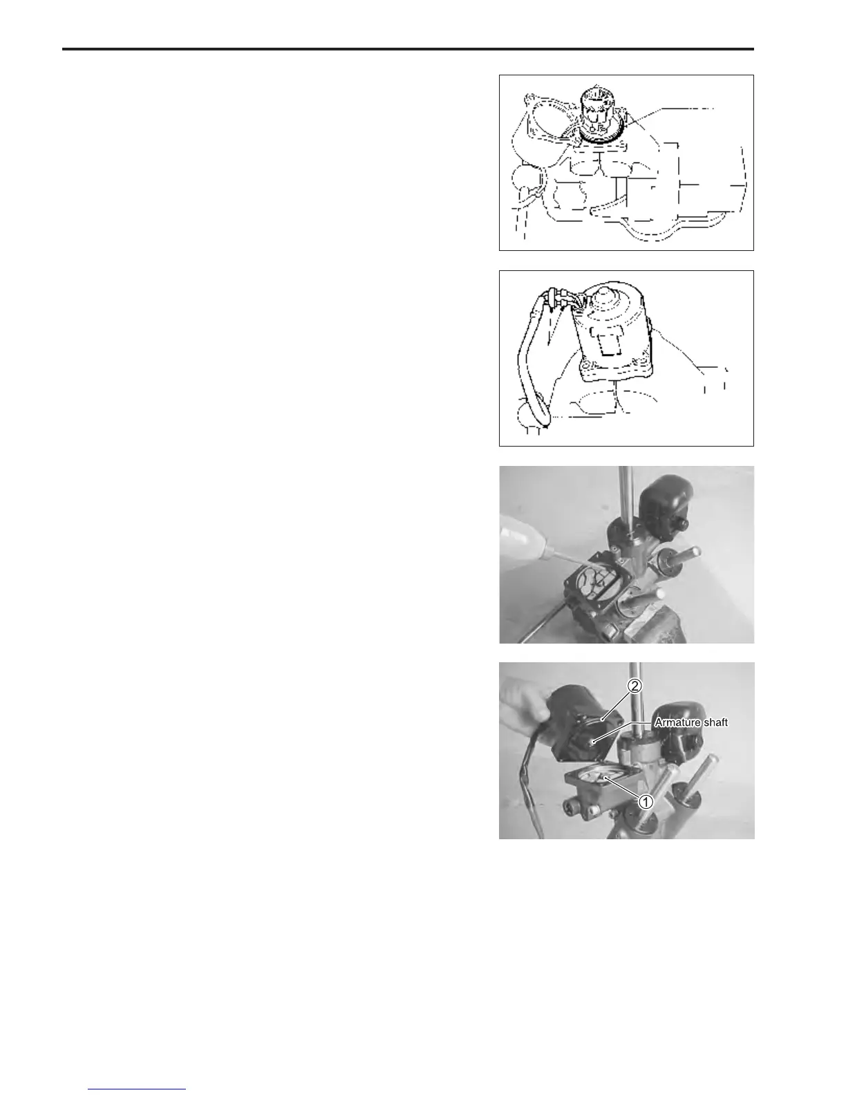
PTT motor installation
Installation is reverse of removal with special attention to fol-
lowing steps.
• Ensure that the drive joint 1 is aligned and firmly inserted
into the gear pump assembly.
• Fit O-ring 2 to PTT motor.
• Check the level of PTT fluid contained in the PTT pump case.
If level is low, add recommended PTT fluid until level with
mating surface of PTT motor.
• Ensure that the faces of the PTT motor and pump unit are
free of dirt or debris.
When attaching the PTT motor to the PTT pump case, en-
sure that the tip of armature shaft fits firmly into the drive joint
1.
• Tighten the four (4) screws to specified torque.
" PTT motor screw: 5 N
.
m (0.5 kg-m, 3.5 lb-ft)
• Pour recommended PTT fluid into reservoir until specified
level.
• Perform the air bleeding procedure.
For air bleeding, see page 25.
 Loading...


