4-18 DRIVE TRAIN
LEFT SIDE SHIM SELECTION
• Install the removed right side shim(s) and differential assem-
bly.
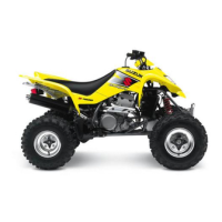
• Put a few pieces of solder (O.D.: 1.2 – 1.5 mm × L: 6 mm) on
the bearing outer race, as shown.
NOTE:
* Do not install the left side shim(s) at this time.
* Apply a small quantity of grease to the solders to prevent them
from falling.
• Assemble the gear case cover and tighten its bolts to the
specified torque in a crisscross pattern. (!4-14)
NOTE:
* Do not apply a sealant to the mating surface of the gear case.
* Do not apply a thread lock to the case cover bolts.
(!4-14)
( Gear case cover bolt: 23 N·m (2.3 kgf-m, 16.5 lb-ft)
• Remove the gear case cover. (!4-4)
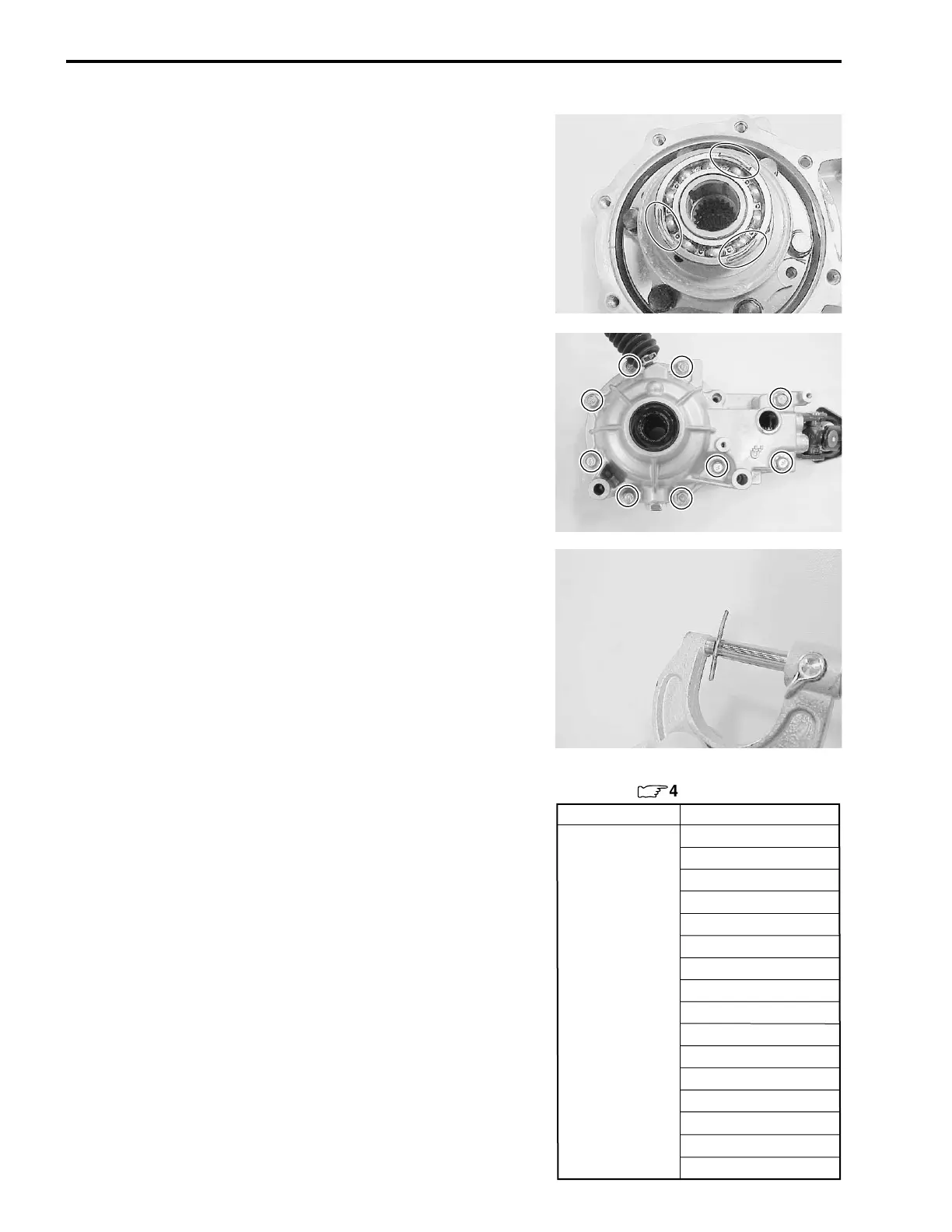
• Measure the thickness of compressed solder with the
micrometer.
# 09900-20205: Micrometer
• Select the proper size of shim(s) from the right chart, accord-
ing as the compressed solder thickness.
• After selecting the proper size of shim(s), check or adjust the
backlash and tooth contact.
Part No.
Shim thickness
For left side of differential
ring gear (
:
4-20)
0.70 mm (0.0276 in)
0.75 mm (0.0295 in)
0.80 mm (0.0315 in)
0.85 mm (0.0335 in)
0.90 mm (0.0354 in)
0.95 mm (0.0374 in)
1.00 mm (0.0394 in)
27445-38FA0 1.05 mm (0.0413 in)
(Shim set: 16 pcs) 1.10 mm (0.0433 in)
1.15 mm (0.0453 in)
1.20 mm (0.0472 in)
1.25 mm (0.0492 in)
1.30 mm (0.0512 in)
1.35 mm (0.0531 in)
1.40 mm (0.0551 in)
1.45 mm (0.0571 in)

 Loading...