ELECTRICAL SYSTEM 14-7
IGNITION SYSTEM
IGNITION SYSTEM PEAK VOLTAGE
INSPECTION
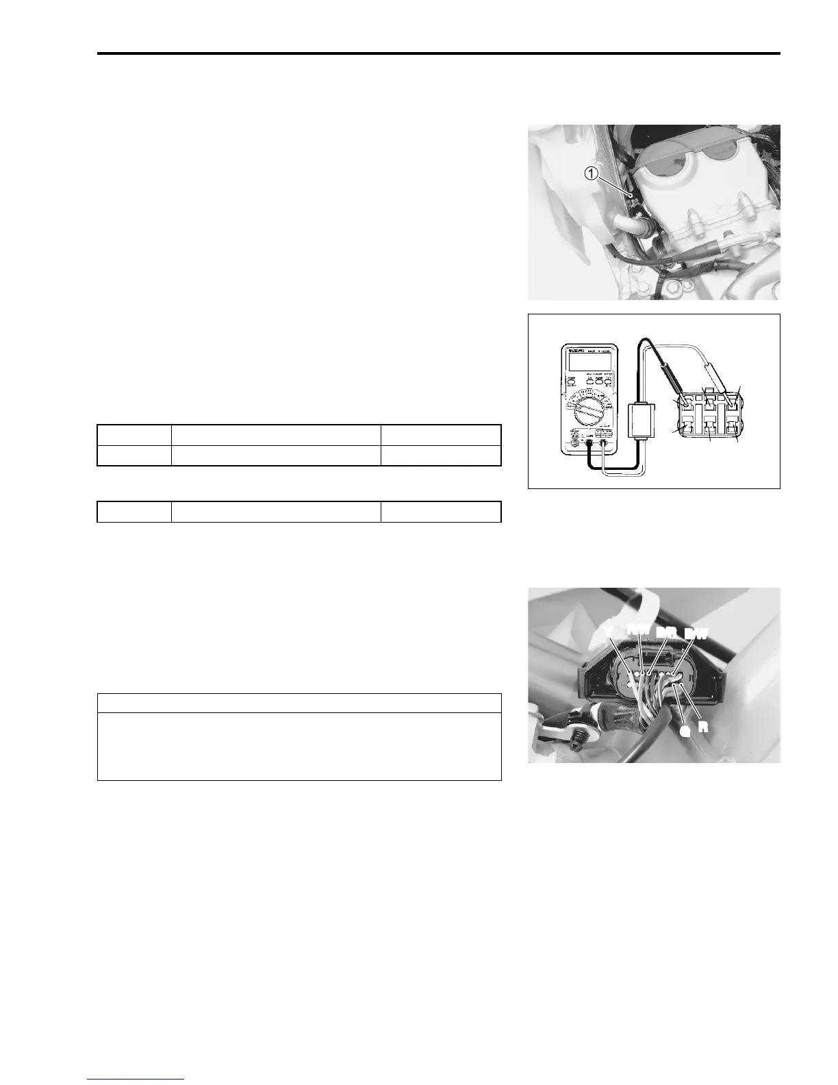
• Disconnect the magneto lead wire coupler
1.
• Connect the multi-circuit tester with peak volt adaptor as
shown.
• Measure the highest peak voltage by depressing the kick
starter lever several times forcefully.
# Stator coil peak voltage
# Pick-up coil peak voltage
! 09900-25008: Multi-circuit tester set
$ Tester knob indication: Voltage (%)
If the peak voltage is below the specification, the cause may lie
in the stator coil or pick up coil. ("14-8)
If the peak voltage is above the specification, check the continu-
ity between the magneto lead wire coupler and CDI unit coupler.
("19-17)
! 09900-25009: Needle pointed probe set
Exciter
+ Black/Red –
- Red/White 25 V and more
Charge
+ Yellow –
- Black/White 8 V and more
Pick-up
+ Red –
- Green 2 V and more
CAUTION
Normally, use the needle pointed probe to the back-
side of the lead wire coupler to prevent the terminal
bend and terminal alignment.

 Loading...


