14-10 ELECTRICAL SYSTEM
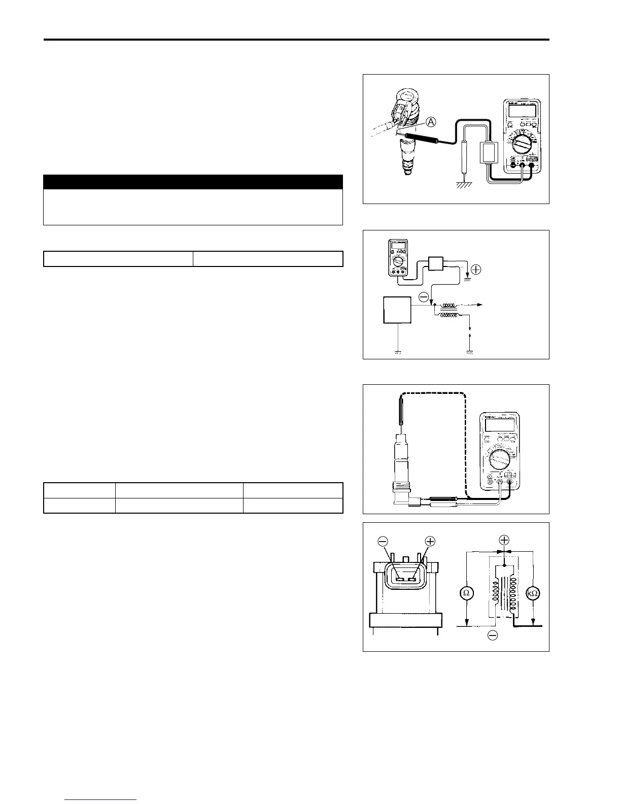
• Insert the needle pointed probe
A to the lead wire coupler.
NOTE:
Use the special tool (needle pointed probe), to prevent the rub-
ber of the water proof coupler from damage.
• Measure the ignition coil primary peak voltage by depressing
the kick starter lever several times forcefully.
# Ignition coil primary peak voltage
! 09900-25008: Multi-circuit tester set
09900-25009: Needle pointed probe set
$ Tester knob indication: Voltage (%)
If the peak voltage is lower than the standard range, check the
ignition coil/plug cap as follow.
IGNITION COIL/PLUG CAP INSPECTION
• Remove the seat, radiator covers and fuel tank. ("5-2)
• Disconnect the ignition coil/plug cap lead wire coupler, and
then remove the ignition coil/plug cap. ("14-9)
• Measure the ignition coil/plug cap resistance.
# Ignition coil/plug cap resistance
! 09900-25008: Multi-circuit tester set
& Tester knob indication: Resistance (Ω)
If the resistance is not within the standard range, replace the
ignition coil/plug cap with a new one.
' WARNING
Do not touch the tester probes and spark plugs to pre-
vent an electric shock while testing.
+ Ground –
- White/Blue 140 V and more
Peak volt
adaptor
CDI
unit
IG. coil
To engine
stop swicth
Primary
+ terminal –
- terminal 0.07 – 0.6 Ω
Secondary Plug cap –
+ terminal 4.8 – 7.1 kΩ

 Loading...


