109
RT Minimum runtime. If the specified cylinder temperature DV is not reached at the
monitored sensor within the time interval for the duration of the runtime
RT, then an
output is switched on for the duration of the runtime
RT and maintained via the
temperature threshold
DV.
Setting range:
0 – 90 min in 1min steps (ex works = 60min)
STT Starting time. The output is enabled from this time for an active function.
Adjustment range: 0 – 23 hour (ex works = 17 hour)
COP Control output. The selected control output 1 or 2 is switched on simultaneously with
the selected output with step 100. This makes it possible to use the auxiliary relay
HIREL-STAG (special accessory) for a burner requirement request.
Important: The corresponding control output must be activated in the COP menu.
Adjustment range: Combinations of all control outputs (ex works = --)
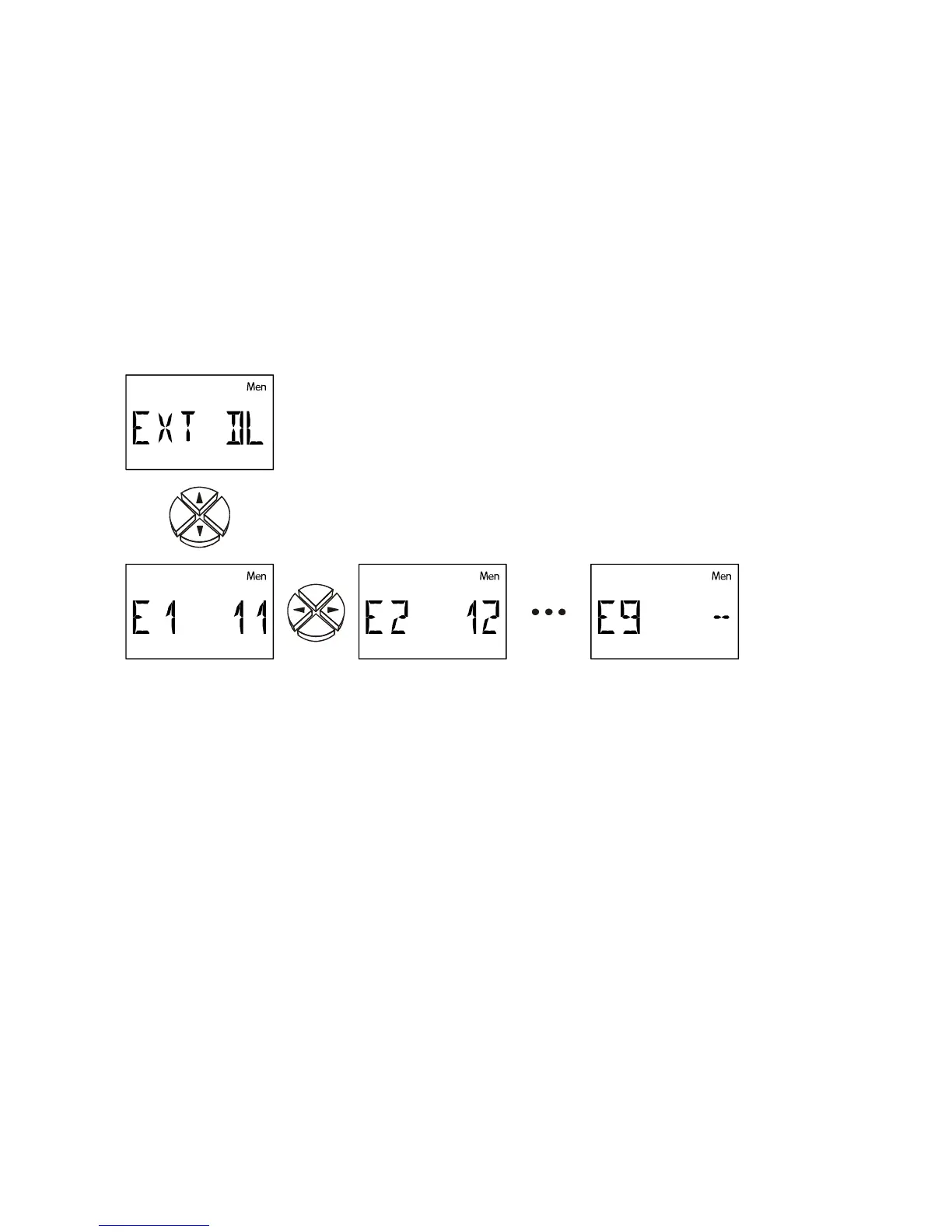
External sensors EXT DL
Address for
External value 1
Address for
External value 2
Address for
External value 9
Electronic sensors for temperature, pressure, humidity, differential pressure, etc. are also
available in the
DL version. In this case, the supply and signal transmission takes place via
the
DL bus.
Up to 9 values from external sensors can be read via the DL bus.
The values of the electronic sensors can be taken from sensor inputs for further control tasks
(adjustment in the SENSOR menu, transfer of values).
E1 -- The external value 1 is deactivated and faded out in the main level.
E1 11 The front number indicates the main address of the external sensor. This can be
set to between 1 and 8 on the sensor according to its operating instructions.
The
rear number indicates the index of the sensor value. Since external sensors
can transmit numerous values the value required from the sensor is defined via
the index.
The setting of the address and index can be taken from the respective data sheets.
Due to the relatively high power requirement, the "
bus load" must be considered:
The controller UVR 61-3 delivers the maximum bus load 100%. For example, the electronic
sensor FTS4-50
DL has a bus load of 39%, therefore up to a max. 2 FTS4-50DL can be
connected to the DL bus. The bus loads of the electronic sensors are listed in the technical
data of the respective sensors.
 Loading...