EasyManua.ls Logo

Technische Alternative UVR61-3 User Manual

Technische Alternative UVR61-3
124 pages
To Next Page IconTo Next Page
To Previous Page IconTo Previous Page
Page #33 background imageLoading...
Page #33 background image
33
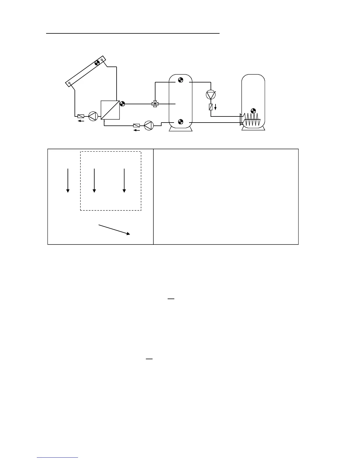
Program 368 - Layered cylinder and feed pump function
Layered system only effective with speed control activated.
(Absolute value control system: AC N1)
Program 368: Solar pumps A1 run when:
S1 is greater than the threshold min1 and S1 is greater than S2 by the difference diff1
and S2 has not exceeded the threshold max1.
The three-way valve A2 switches up when:
S5 is greater than the threshold min2 or S5 is greater than S4 by the difference diff2
and S4 has not exceeded the threshold max2.
The feed pump A3 runs when:
S4 is greater than the threshold min3 and S4 is greater than S3 by the difference diff3
and S3 has not exceeded the threshold max3.
A1 = S1 > (S2 + diff1) & S1 > min1 & S2 < max1
A2 = (S5 > min2 or S5 > (S4 + diff2)) & S4 < max2
A3 = S4 > (S3 + diff3) & S4 > min3 & S3 < max3
Program 369: If S4 has reached max2, the quick warm-up phase has been completed, and
the speed control is thus blocked
optimal efficiency.
If PSC (pump speed control) is activated, the speed level is set to the maximum level, if
control output 1 is activated; the analog level for the maximum speed is output. Control
output 2 is not changed and continues control.
S1 S5 S5
min1 <min2 >min2
A2
S2 S4 S4
max1 max2 max2
min3
S3
max3
diff3
A3
diff1
A1
diff2
A2
Required settings:
max1 … limit CYL 1 S2 A1
max2 … limit CYL 1 S4 A2
max3 … limit CYL 2 S3 A3
min1 … switch-on temp. coll. S1 A1
min2 … switch-on temp.ssl. S5 A2
min3 … switch-on temp. CYL 1 S4 A3
diff1 … coll. S1 – CYL 1 S2 A1
diff2 … supply l. S5 – CYL 1 S4 A2
diff3 … CYL 1 S4 – CYL 2 S3 A3
CYL 1 CYL 2
A1
A2
S1
S2
S4
A1
S5
S3
A3

Table of Contents

Other manuals for Technische Alternative UVR61-3

Questions and Answers:

Technische Alternative UVR61-3 Specifications

General IconGeneral
BrandTechnische Alternative
ModelUVR61-3
CategoryDryer
LanguageEnglish

Summary

Safety requirements

Maintenance

Details on how to maintain the system, including cleaning instructions and spare parts correspondence.

Generally applicable rules for the proper use of this unit

Rules for proper use, including specific guidance for swimming pool and solar thermal systems.

Setting for "Step by step" control

Hydraulic diagrams

Installation instructions

Installing the sensors

Guidance on proper arrangement and installation of sensors for system functionality.

Sensor lines

Information on extending sensor lines and proper connection techniques to prevent measurement fluctuations.

Installing the unit

Instructions for safely opening the unit case and mounting it to a wall.

Electrical connection

Guidelines for electrical connection by a professional electrician, including safety notes.

Special connections

Details on control outputs, sensor input S6, data link, and switching output 3 to potential-free.

Operation

The main level

Overview of the main display level, including icons for temperature, volume flow, and status.

Changing a value (parameter)

Procedure for changing parameter values using navigation keys and saving changes.

The parameter menu Par

Overview of the parameter menu, including code entry, version, program number, and settings.

Brief description

Explanation of parameter menu items like CODE, VER, PR, LO, PA, and set value types.

The menu Men

Brief description

Description of menu functions like ENGL, CODE, SENSOR, SYS PF, STARTF, PRIOR, ART, PSC, COP, F CHCK, HQC, LEGION, EXT DL, DRAINB.