EasyManua.ls Logo

Technische Alternative UVR61-3 User Manual

Technische Alternative UVR61-3
124 pages
To Next Page IconTo Next Page
To Previous Page IconTo Previous Page
Page #74 background imageLoading...
Page #74 background image
74
Timer function TIMER
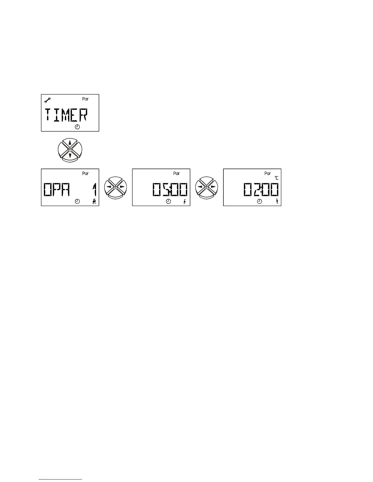
Setting the Timer function
The timer function can be assigned to any output.
It is possible to specify a release time (during this time the output is released) and a block
time (during this time the output is blocked).
Release time and block time are active
alternatively.
Assigned
outputs
Release time Block time
In the example the timer function is assigned to output 1. The output is released for 5 hours
and blocked for 2.
To the timer function are assigned the following outputs. (ex works = --)
OPA A (AND) During the release time the respective program determines the status of
the selected outputs. During the block time they remain deactivated.
OPO O (OR) The selected outputs are released during the release time. During the
block time the respective program determines the output status.
Setting range: Combination of all outputs (e.g. OP1, OP 23, OP 123)
OPA 1 to OPA123 and OPO 1 to OPO 123
OP -- = no output (timer function deactivated)
 Period for which the set outputs are enabled (ex works = 00.00)
Setting range: 00.00 to 23.50 in 10 min increments
 Period for which the set outputs are blocked (ex works = 00.00)
Setting range: 00.00 to 23.50 in 10 min increments

Table of Contents

Other manuals for Technische Alternative UVR61-3

Questions and Answers:

Technische Alternative UVR61-3 Specifications

General IconGeneral
BrandTechnische Alternative
ModelUVR61-3
CategoryDryer
LanguageEnglish

Summary

Safety requirements

Maintenance

Details on how to maintain the system, including cleaning instructions and spare parts correspondence.

Generally applicable rules for the proper use of this unit

Rules for proper use, including specific guidance for swimming pool and solar thermal systems.

Setting for "Step by step" control

Hydraulic diagrams

Installation instructions

Installing the sensors

Guidance on proper arrangement and installation of sensors for system functionality.

Sensor lines

Information on extending sensor lines and proper connection techniques to prevent measurement fluctuations.

Installing the unit

Instructions for safely opening the unit case and mounting it to a wall.

Electrical connection

Guidelines for electrical connection by a professional electrician, including safety notes.

Special connections

Details on control outputs, sensor input S6, data link, and switching output 3 to potential-free.

Operation

The main level

Overview of the main display level, including icons for temperature, volume flow, and status.

Changing a value (parameter)

Procedure for changing parameter values using navigation keys and saving changes.

The parameter menu Par

Overview of the parameter menu, including code entry, version, program number, and settings.

Brief description

Explanation of parameter menu items like CODE, VER, PR, LO, PA, and set value types.

The menu Men

Brief description

Description of menu functions like ENGL, CODE, SENSOR, SYS PF, STARTF, PRIOR, ART, PSC, COP, F CHCK, HQC, LEGION, EXT DL, DRAINB.