59
Hot water sensor: When the control system is used in hot water systems with an external
heat exchanger and variable-speed pump, changes in the amount of temperature have to be
reacted to quickly. Hence, the hot water sensor has to be put directly on the heat
exchanger’s outlet. A t-shaped connector should be used to insert the ultrafast sensor
(special accessory) in the outlet using an O-ring along the NIRO tube (inoxydable). The heat
exchanger has to be installed upright with the hot water outlet on top.
Radiant heat sensor: To get a measurement according to the collector’s position, it
should be parallel to the collector. It should thus be screwed onto the metal sheet or next to
the collector along an extension of the assembly rail. To this end, the sensor case has a
blind hole that can be opened at any time.
Space sensor: This sensor is intended for installation in floor space (as a reference
space). The space sensor should not be near a source of heat or near a window.
Outdoor temperature sensor: This sensor is installed on the coldest wall side (usually the
north) some two meters above ground.
Avoid temperature influences from nearby air shafts,
open windows, etc.
Sensor lines
All of the sensor lines with a cross-section of 0.5mm2 can be extended up to 50m. With this
length of line and a Pt1000 temperature sensor, the measurement error is approx. +1K.
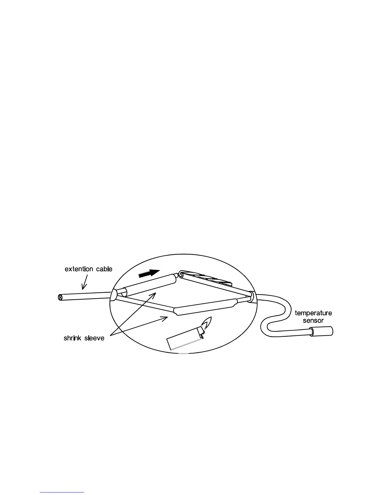
Longer lines or a lower measurement error require an appropriately larger cross-section. The
sensor and the probe can be connected by putting the heat-shrinkable sleeve truncated to 4
cm over a wire and twisting the bare ends. If one of the wire ends is tinned then the
connection must be made through soldering. Then the heat-shrinkable sleeve is put over the
bare, twisted ends and carefully heated (such as with a lighter) until it has wrapped the
connection tightly.
In order to prevent measurement fluctuations, the sensor cables must not be subject to
negative external influences to ensure fault-free signal transmission. When using non-
screened cables, sensor cables and 230V network cables must be laid in separate cable
channels and at a minimum distance of 5 cm.
 Loading...