22
All programs +2: If both cylinders have reached their maximum temperature due to the solar
power system, pumps
A2 and A3 are switched on (reverse cooling function)
All programs +4:
Both solar loops have separate switch-on thresholds at S1:
Output
A1 retains min1, and A2 switches at min3.
The priorities for CYL 1 and CYL 2 can be set in the parameter menu under PA. In addition,
a solar priority function can be set for this diagram in the menu
PRIOR (see solar priorities for
more details).
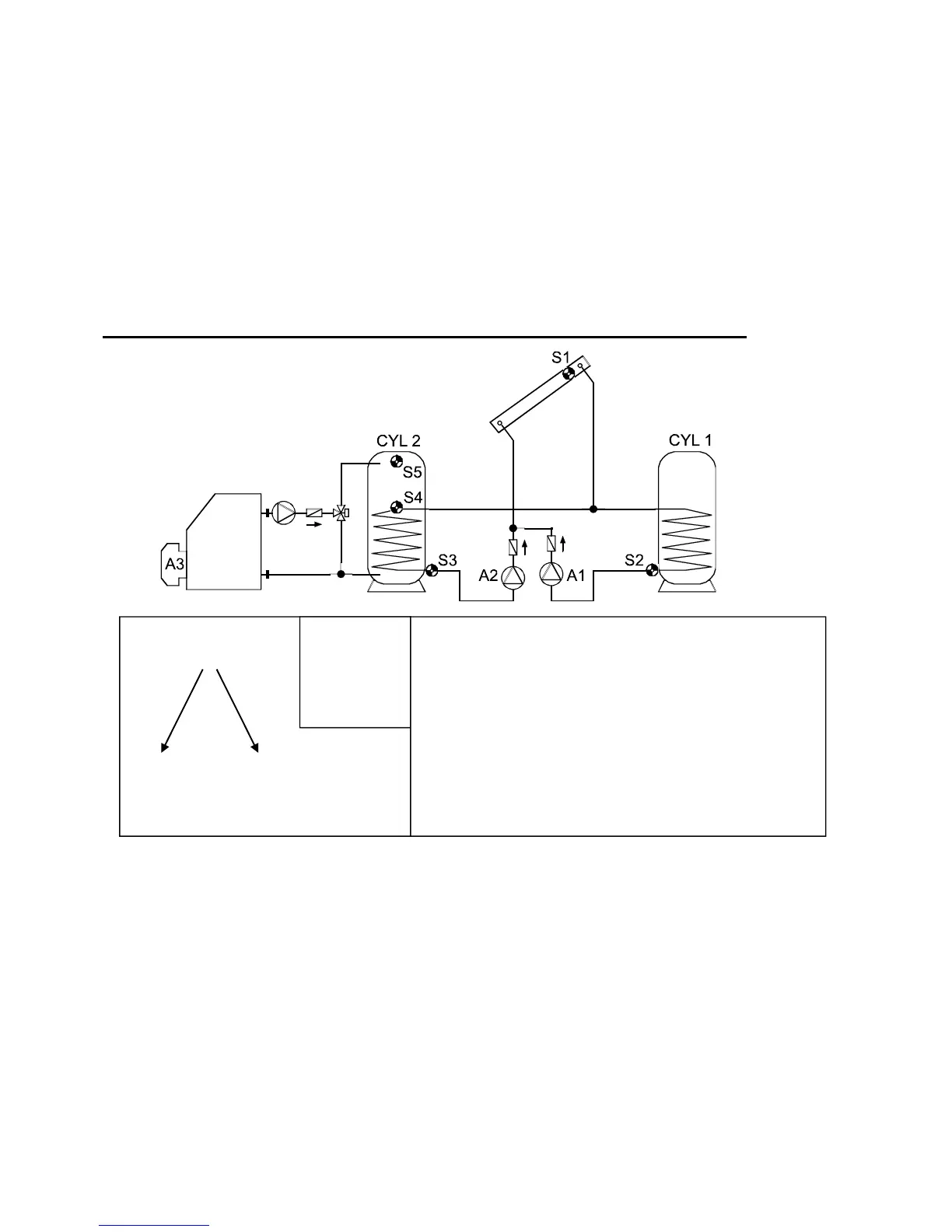
Program 208 - Solar power system with 2 consumers and burner requirement
Program 208: Pump A1 runs when:
S1 is greater than the threshold min1 and S1 is greater than S2 by the difference diff1
and S2 has not exceeded the threshold max1.
Pump A2 runs when:
S1 is greater than the threshold min1 and S1 is greater than S3 by the difference diff2
and S3 has not exceeded the threshold max2.
Output A3 switches on when S5 falls below threshold min3.
Output
A3 switches off (dominant) when S4 exceeds max3.
A1 = S1 > (S2 + diff1) & S1 > min1 & S2 < max1
A2 = S1 > (S3 + diff2) & S1 > min1 & S3 < max2
A3 (on) = S5 < min3 A3 (off) = S4 > max3
S1
min1
S2 S3
max1 max2
diff2
A2
diff1
A1
Burner
A3
S5 min3
S4 max3
Required settings:
max1 … limit CYL 1 S2 A1
max2 … limit CYL 2 S3 A2
max3 … burner req. off CYL 2 S4 A3
min1 … switch-on temp. coll. S1 A1, A2
min2
… see all programs +4
min3 … burner req. on CYL 2 S5 A3
diff1 … coll. S1 – CYL 1 S2 A1
diff2 … coll. S1 – CYL 2 S3 A2
 Loading...